drt2_devicenet_q102-e1_20_22_csm2147.pdf - 第91页
71 MULTIPLE I/O TERMINAL Series MULTIPLE I/O T ERMINAL Series ........... ...................... ....................... ................ 72 ■ MUL TIPLE I/O TERMINAL Configuration Example Communications Unit............ …
70 Ordering Information
Ordering Information
*1. The End Unit is sold separately. (End Units are not included with Communications Units.)
*2. Use the GCN2-100 as a set with the GRT1-TBR and GRT1-TBL.
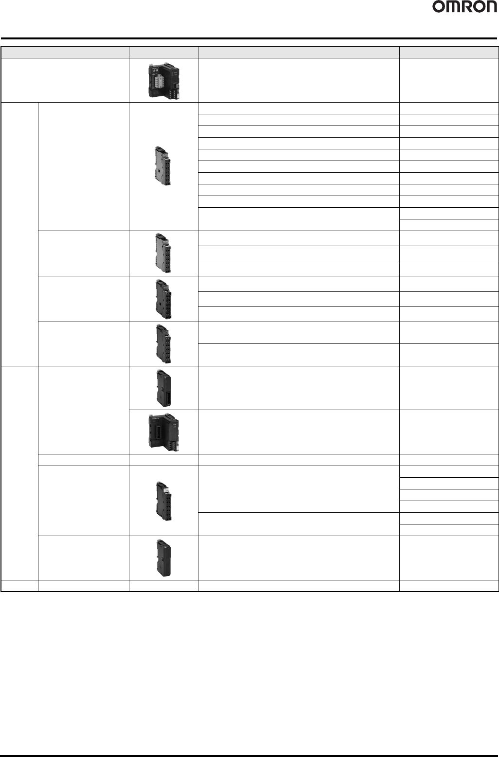
Name Appearance Specifications Model
DeviceNet Communications Unit Up to 64 SmartSlice I/O Units can be connected (1,024 I/O points). GRT1-DRT
SmartSlice
I/O Units
Digital I/O Units
4 inputs, NPN GRT1-ID4
4 inputs, PNP GRT1-ID4-1
4 outputs, NPN GRT1-OD4
4 outputs, PNP GRT1-OD4-1
8 inputs, NPN GRT1-ID8
8 inputs, PNP GRT1-ID8-1
8 outputs, NPN GRT1-OD8
8 outputs, PNP GRT1-OD8-1
2 relay outputs GRT1-ROS2
4 AC inputs
GRT1-IA4-1
GRT1-IA4-2
Analog I/O Units
2 inputs (current or voltage) GRT1-AD2
2 outputs (current) GRT1-DA2C
2 outputs (voltage) GRT1-DA2V
Temperature Input Unit
(resistance thermometer)
2 temperature inputs (Pt100 resistance thermometer) GRT1-TS2P
2 temperature inputs (Pt1000 resistance thermometer) GRT1-TS2PK
2 thermocouple inputs GRT1-TS2T
Counter Units
1 counter input, 1 external output, NPN GRT1-CT1
1 counter input, 1 external output, PNP GRT1-CT1-1
System
Units
Turnback Units
For right-side turnback
(Used to divide a SmartSlice I/O Terminal into blocks)
GRT1-TBR
For left-side turnback
(Used to divide a SmartSlice I/O Terminal into blocks)
GRT1-TBL
Turnback Cable -- Length: 1 m GCN2-100
I/O Power Feed Unit
Used if the total current consumption of the I/O Power Supply exceeds
4 A or to use a separate I/O power supply.
GRT1-PD2
GRT1-PD2G
GRT1-PD8
GRT1-PD8-1
Used to add V and G terminals for the I/O power supply.
GRT1-PC8
GRT1-PC8-1
End Unit *1 Required at the end of SmartSlice I/O Terminals. GRT1-END
Option
Terminal blocks -- Terminal blocks (5 blocks) GRT1-BT1-5

71
MULTIPLE I/O TERMINAL Series
MULTIPLE I/O TERMINAL Series
........................................................................ 72
■ MULTIPLE I/O TERMINAL Configuration Example
Communications Unit....................................................................................... 73
DRT1-COM
Digital I/O Units................................................................................................ 74
GT1-@D16(-1)/@D16MX(-1)/@D16ML(-1)/@D32ML(-1)/@D16DS(-1)
Relay Output Units........................................................................................... 81
GT1-ROS16/ROP08/FOP08
Analog I/O Units............................................................................................... 83
GT1-AD/DA
Temperature Input Units.................................................................................. 85
GT1-TS04
@
72 MULTIPLE I/O TERMINAL Series
MULTIPLE I/O TERMINAL Series
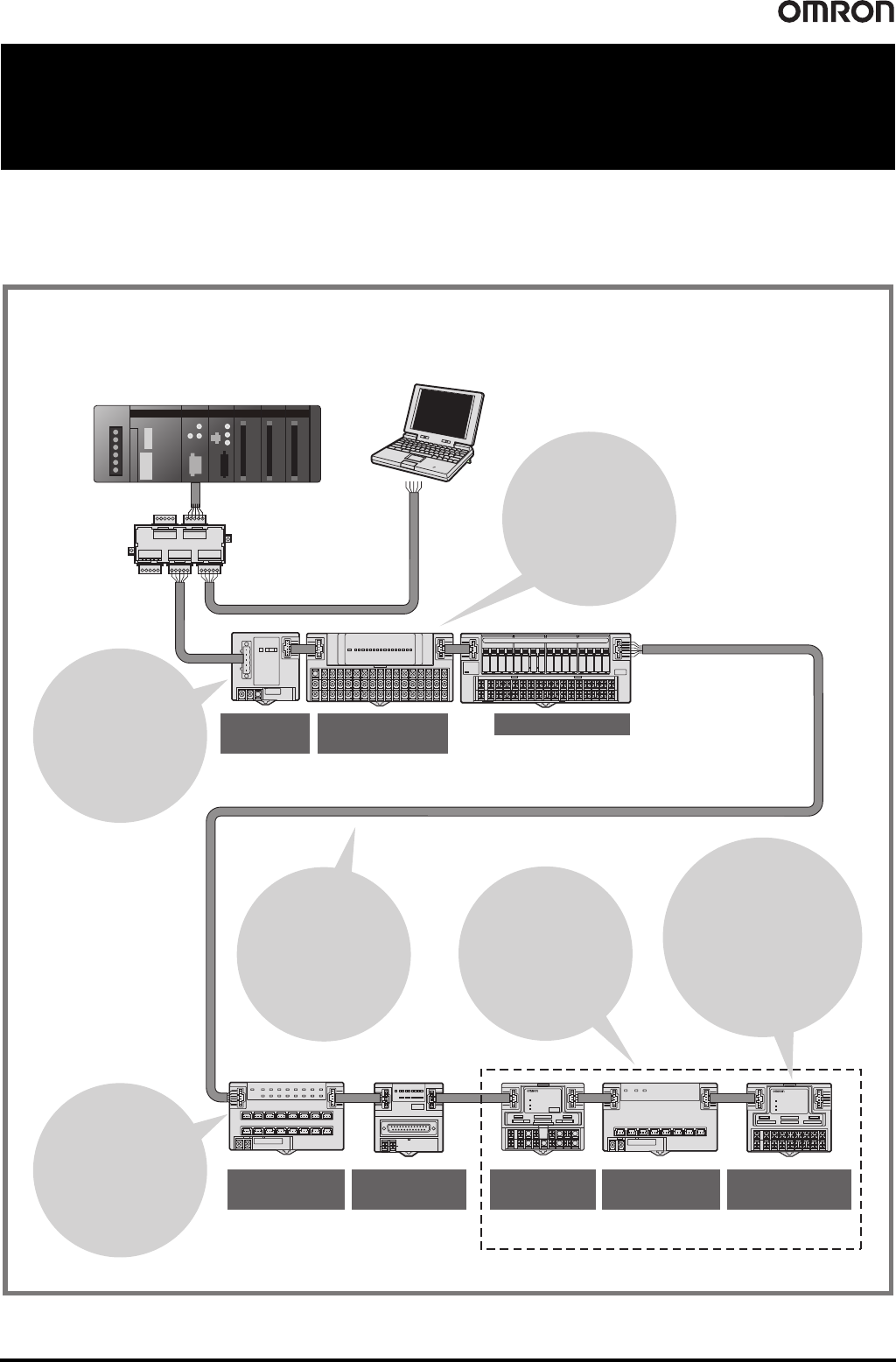
A MULTIPLE I/O TERMINAL with a flexible combination of numerous versatile I/O Units handles digital I/O, analog I/O,
counter inputs, or relay outputs and boosts on-site productivity higher than ever. Using a MULTIPLE I/O TERMINAL, one
Slave (Communications Unit) can connect to a maximum of eight I/O Units to achieve control of a maximum of 1,024 I/O
points. (see Note below.)
* By using the DeviceNet Configurator (sold separately), control can be performed for up to 32,000 points for CJ1W-DRM21 and CS1W-DRM21-V1 DeviceNet Units, and 4,800
points for C200HX/HG/HE Master Units.
Note: The number of I/O points under control may be restricted by the application. Refer to the DeviceNet MULTIPLE I/O TERMINAL Operation Manual (W348) for details.
MULTIPLE I/O TERMINAL Configuration Example
Master Unit
(CS/CJ Series C200HX/HG/HE (-ZE),
C200HS Series *)
Terminal Extension Cable
Approx. 3 m (1 m between Units)
T-branch Tap
Digital I/O Units with
Terminal Blocks
Analog I/O Units
with Connectors
Analog I/O Units
with Terminal Blocks
Digital I/O Units
with Connectors
Communi-
cations Unit
DRT1-COM
GT1-ID/OD16(-1)
GT1-ROS16/
ROP08/FOP08
GT1-AD08MX
GT1-DA04MX
GT1-ID/OD16MX(-1)
GT1-AD04
GT1-DA04
Digital I/O Units
with Connectors
GT1-ID/OD16ML(-1)
GT1-ID/OD16DS(-1)
GT1-ID/OD32ML(-1)
Extension cable
can be used so the
mounting positions
of individual Units
can be flexible.
Maintenance of
parameter settings
can be performed
easily using the
Configurator.
The circuit
section is
detachable, so
wiring can be
maintained just
as it is.
GT1-DA04
Units can be
combined for flexible
numbers of I/O points
Also, in addition to input
and output, analog
and digital can be
combined.
The connector
method makes it
easy to remove and
install I/O devices
such as sensors.
Up to eight Units
can be connected
to a single
Communications
Unit (Slave).
Relay Output Units
GT1-TS04T
GT1-TS04P
Temperature
Input Units
GT1-TS04T
IN
Configurator
Ver. 2.@