drt2_devicenet_q102-e1_20_22_csm2147.pdf - 第110页
90 Programmab le Slaves CPM2C-S1 @ 0C-DRT Communications Specifications ● DeviceNet *1. Terminating resistance is required at both ends of the trunk line. *2. This value applies when using Thick Cable for the trunk line.…
Programmable Slaves CPM2C-S1@0C-DRT 89
General Specifications and Performance Specifications
* A Connecting Cable (CPM2C-CN111, CS1W-CN114, or CS1W-CN118) is required to connect to the communications (peripheral/RS-232C) port.
Item Specifications
Control method Stored program method
I/O control method Cyclic scan method (Immediate refreshing can be performed with IORF instruction.)
Programming language Ladder diagram
Instruction length 1 step per instruction, 1 to 5 words per instruction
Instructions
Basic instructions 14 instructions
Special instructions 105 instructions, 185 variations
Execution
time
Basic instructions 0.64 s (LD instruction)
Special instructions 7.8 s (MOV instruction)
Program capacity 4,096 words
Maximum I/O points
CPU Unit only: 10 points
Expansion I/O: 96 points (32-point Expansion I/O Unit × 3)
CompoBus/S: 256 points (362 in total)
Input bits IR 00000 to IR 00915 (Bits not used for input bits can be used for work bits.)
Output bits IR 01000 to IR 01915 (Bits not used for output bits can be used for work bits.)
CompoBus/S input bits 128 bits: IR 02000 to IR 02715 (Words IR 020 to IR 027)
CompoBus/S output bits 128 bits: IR 03000 to IR 03715 (Words IR 030 to IR 037)
Work bits
672 bits: IR 02800 to IR 02915 (Words IR 028 to IR 029)
IR 03800 to IR 03915 (Words IR 038 to IR 039)
IR 04000 to IR 04915 (Words IR 040 to IR 049)
IR 20000 to IR 22715 (Words IR 200 to IR 227)
Special bits (SR area) 440 bits: SR 22800 to SR 25507 (Words IR 228 to IR 225)
Temporary bits (TR area) 8 bits (TR0 to TR7)
Holding bits (HR area) 320 bits: HR 0000 to HR 1915 (Words HR 00 to HR19)
Auxiliary bits (AR area)
384 bits: AR 0000 to AR 2315 (Words AR 00 to AR23)
These include the CompoBus/S slave status flags (AR 04 to 07).
Link bits (LR area) 256 points: LR 0000 to LR 1515 (Words LR 00 to LR 15)
Timers/Counters
256 timers/counters: TIM/CNT 000 to TIM/CNT 255
1-ms timers: TMHH
10-ms timers: TIMH
100-ms timers: TIM
1-s/10-s timers: TIML
Decrementing counters: CNT
Reversible counters: CNTR
Data memory
Read/Write
2,048 words (DM 0000 to DM 2047)
The Error Log is contained in DM 2000 to DM 2021.
Read-only 456 words (DM 6144 to DM 6599)
PC Setup 56 words (DM 6600 to DM 6655)
DeviceNet slave functions
DeviceNet Remote I/O Link
• Use up to 1,024 I/O points in the I/O Link.
Explicit Message Communications
• Any PC data area can be accessed from the master.
Basic
interrupt
functions
Interrupt inputs 2 interrupts (Used for both counter mode interrupt inputs and quick-response inputs.)
Scheduled interrupts 1 interrupt
High-speed
counter
functions
High-speed counters 1 counter (20 kHz single-phase or 5 kHz 2-phase)
Counter interrupts 1 interrupt (set value comparison or set-value range comparison)
Interrupt inputs (counter
mode)
2 interrupts (Used for both external interrupt inputs and quick-response inputs.)
Count-up interrupts 2 interrupts (Used for both external interrupt inputs and quick-response inputs.)
Quick-response inputs
2 inputs
(Used for both external interrupt inputs and counter mode interrupt inputs.)
Min. input pulse width: 50 s max.
Pulse output
2 points without acceleration/deceleration, 10 Hz to 10 kHz each, and no direction control;
1 point with trapezoid acceleration/deceleration, 10 Hz to 10 kHz, and direction control;
2 points with variable duty-ratio outputs
Synchronized pulse control 1 point
Input time constant
(ON response time = OFF response time)
Can be set for CPU inputs and Expansion Unit inputs only.
(1 ms, 2 ms, 3 ms, 5 ms, 10 ms, 20 ms, 40 ms, or 80 ms)
Clock Equipped with clock (built-in RTC)
Communications functions
Peripheral port: Supports Host Link, peripheral bus, no-protocol, or Programming Console connections.
RS-232C port: Supports Host Link, no-protocol, 1:1 Link, or 1:1 NT Link connections.
Memory protection HR area, AR area, program contents, DM area contents, and counter values maintained during power interruptions.
Memory backup
Non-volatile (flash) memory: Program, read-only DM area, and PC Setup
Memory backup (lithium battery; 2-year lifetime): DM area, HR area, AR area, and counter values
Self-diagnostic functions CPU errors (watchdog timer), memory errors, communications errors, setting errors, battery errors, and expansion I/O bus errors
Program checks No END instruction, programming errors (checked when operation is started)
Programming
Devices
Programming Console C200H-PRO27
CX-Programmer Windows edition
90 Programmable Slaves CPM2C-S1@0C-DRT
Communications Specifications
● DeviceNet
*1. Terminating resistance is required at both ends of the trunk line.
*2. This value applies when using Thick Cable for the trunk line.
If Thin Cable is used, the value will be 100 m max.
● CompoBus/S
*1. Connect external terminating resistance.
*2. Switched using DM area setting. (Default setting: 750 kbps.)
*3. If the number of slaves connected is 16 or less, the maximum main line length
will be 100 m max., and the maximum total branch line length will be 50 m max.
*4. There are no restrictions on the branching configuration, main line length,
branch line length, or total branch line length. Connect external terminating
resistance to the node farthest from the master.
Cables for I/O Connector
● Cables for Connector - Terminal Conversion Units
Dimensions (Unit: mm)
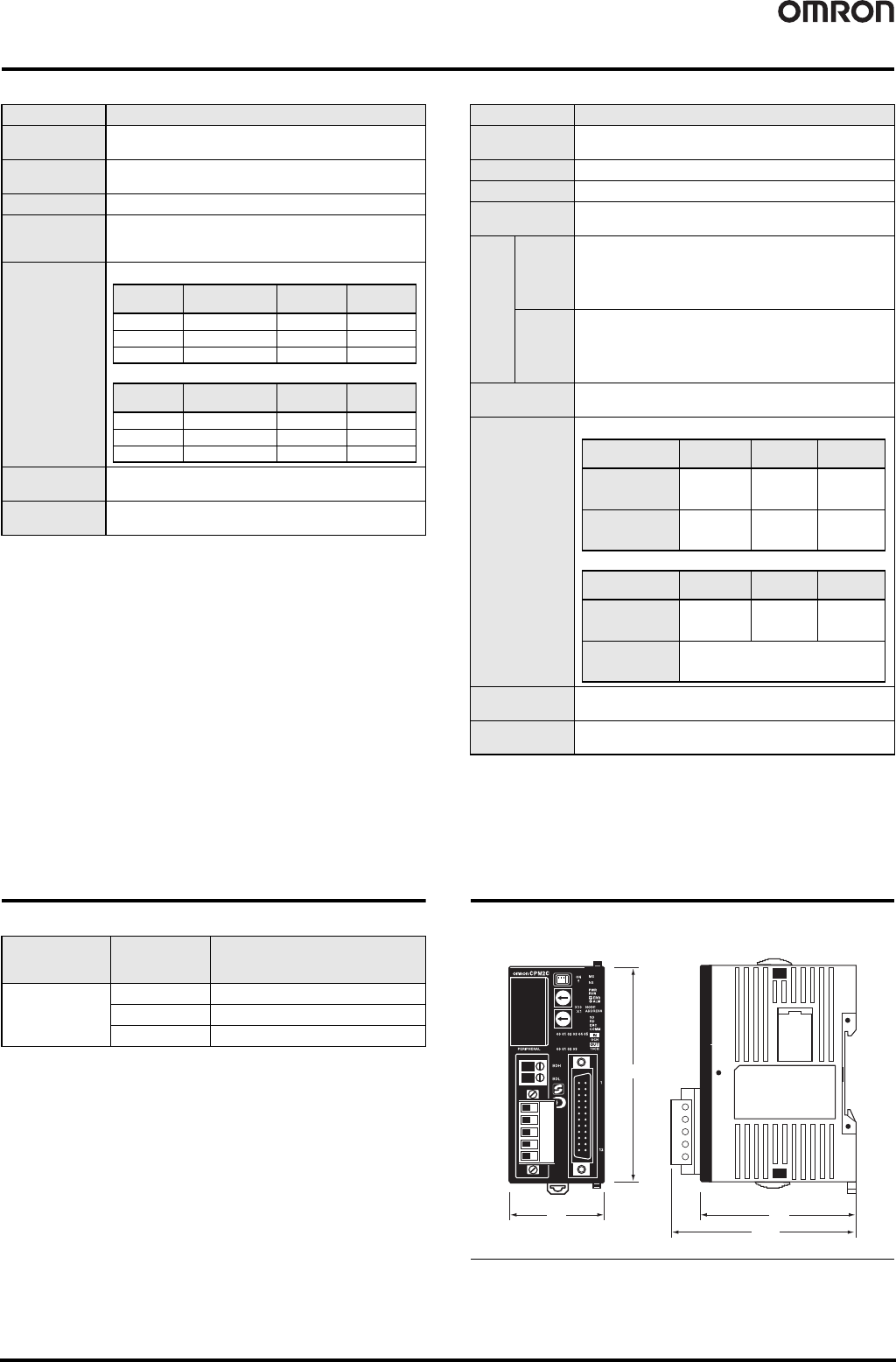
Item Specifications
Communications
protocol
Conforms to DeviceNet
Connection form
*1
Combination of multi-drop method and T-branch connections
(for trunk and drop lines)
Baud rate 500, 250, or 125 kbps
Communications
media
Special 5-wire cable (2 signal lines, 2 power supply lines,
1 shield line)
4-wire Special Flat Cable (2 signal lines and 2 power lines)
Communications
distance
Communications
power supply
24 VDC is supplied externally.
Maximum number
of nodes
64 (including Masters, Slaves, and the Configurator)
• Using special 5-wire Flat Cable
• Using special 4-wire Flat Cable
Baud rate
Network length
(max.)
Branch line
length
Total branch
line length
500 kbps 100 m max. *2 6 m max. 39 m max.
250 kbps 250 m max. *2 6 m max. 78 m max.
125 kbps 500 m max. *2 6 m max. 156 m max.
Baud rate
Network length
(max.)
Branch line
length
Total branch
line length
500 kbps 75 m max. 6 m max. 35 m max.
250 kbps 150 m max. 6 m max. 48 m max.
125 kbps 265 m max. 6 m max. 135 m max.
Item Specifications
Communications
protocol
Special CompoBus/S protocol
Coding method Manchester coding
Connection form Multi-drop method and T-branch connections *1
Baud rate
High-speed Communications Mode: 750 kbps
Long-distance Communications Mode: 93.75 kbps *2
Com-
muni-
cations
cycle
time
High-
speed
Commu-
nications
Mode
0.5 ms (with 8 input and 8 output slaves connected)
0.8 ms (with 16 input and 16 output slaves connected)
Long-dis-
tance
Commu-
nications
Mode
4.0 ms (with 8 input and 8 output slaves connected)
6.0 ms (with 16 input and 16 output slaves connected)
Communications
media
2-wire cable (VCTF 0.75 x 2),
4-wire cable (VCTF 0.75 x 4), or Special Flat Cable
Communications
distance
Maximum number
of nodes
32
Error control
checks
Manchester code check, frame length check, and parity check
• 2-wire VCTF cable
• 4-wire VCTF cable or Special Flat Cable
Communications
mode
Main line
length
Branch line
length
Total branch
line length
High-speed
Communications
Mode
100 m max. 3 m max. 50 m max.
Long-distance
Communications
Mode
500 m max. 6 m max.
120 m
max.
Communications
mode
Main line
length
Branch line
length
Total branch
line length
High-speed
Communications
Mode *3
30 m max. 3 m max. 30 m max.
Long-distance
Communications
Mode *4
Free branching
(up to a total cable length of 200 m)
Cable
Connected
product
Connector Products (Connector-
Terminal Block Conversion Units)
Connecting method
XW2Z-@@@A
XW2R-J20G-T Phillips screw M3
XW2R-E20G-T Slotted screw M3
XW2R-P20G-T Push-in spring
40 65
(77)
90
CPM2C-S100C-DRT
CPM2C-S110C-DRT

91
Intelligent Slaves
Digital Sensor Communications Unit ............................................................... 92
E3X-DRT21-S VER.3
DeviceNet ID Slave.......................................................................................... 94
V600-HAM42-DRT
DeviceNet ID Slave.......................................................................................... 95
V680-HAM42-DRT
DeviceNet-compliant Digital Indicators ............................................................ 96
K3HB-@-DRT
DeviceNet-compliant Digital Controllers ........................................................ 100
E5AR-DRT/E5ER-DRT
DeviceNet Communications Unit for Modular Temperature Controller.......... 104
EJ1-DRT
Multi-function Compact Inverter MX2-Series V1 type DeviceNet Communication Unit
..... 107
3G3AX-MX2-DRT-E
High-function General-purpose Inverters RX-Series V1 type DeviceNet Communication Unit
.. 108
3G3AX-RX-DRT-E