drt2_devicenet_q102-e1_20_22_csm2147.pdf - 第81页
Temperature Input Terminals DRT2-TS04 @ 61 P erformance Specifications *1. A current of 0.35 mA flows to sensors connected to the DRT2-TS04P. *2. The indicator accuracy specifications differ depending on the mounting dir…
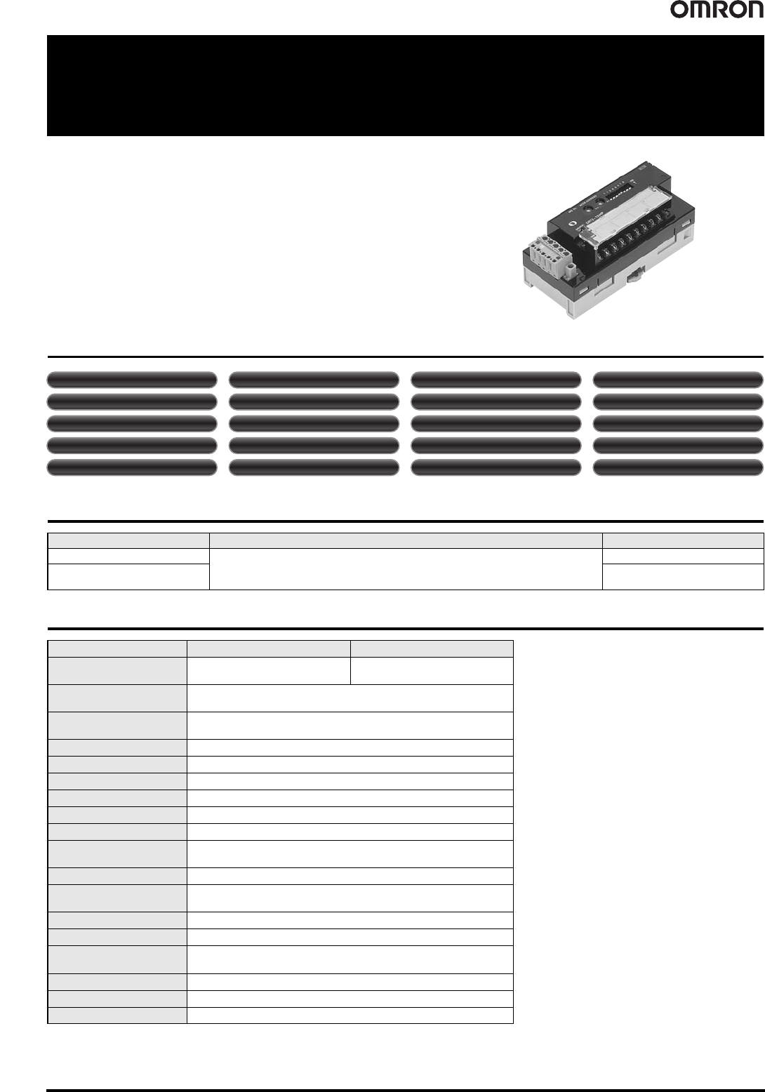
60 Temperature Input Terminals DRT2-TS04@
Temperature Input Terminals
DRT2-TS04@
Temperature Input Terminal with Smart
Functionality
• The Temperature Input Terminal can be used with almost the same functionality as a
Analog Input Terminal, such as with scaling and comparator functions.
• Enhanced performance is provided with functionality specific to the Temperature
Input Terminal, such as the recording the operating time in a preset temperature
range and temperature difference detection between input channels.
Smart Slave Functions
Ordering Information
General Specifications
Input type I/O points Model
Thermocouple input
4 inputs allocated 4 input words at the Master Unit
(8 input words allocated when 1/100 display mode is selected).
DRT2-TS04T
Platinum-resistance
thermometer input
DRT2-TS04P
Item Model DRT2-TS04T DRT2-TS04P
Input type Thermocouple input
Platinum-resistance thermometer
input
I/O points
4 inputs allocated 4 input words at the Master Unit
(8 input words allocated when 1/100 display mode is selected)
Communications power
supply voltage
11 to 25 VDC (Supplied from the communications connector)
Current consumption 70 mA max. (24 VDC), 110 mA max. (11 VDC)
Noise immunity Conforms to IEC61000-4-4, 2.0 kV
Vibration resistance 10 to 150 Hz, 0.7-mm single amplitude
Shock resistance 150 m/s
2
Dielectric strength 500 VAC (between isolated circuits)
Insulation resistance 20 MΩ min. (initial value) at 100 VDC
Ambient operating
temperature
-10°C to 55°C (with no icing or condensation)
Ambient operating humidity 25% to 85%
Ambient operating
atmosphere
No corrosive gases
Ambient storage temperature -25°C to 65°C
Mounting method DIN 35 mm-track mounting
Mounting strength
50 N
10 N (in the DIN Track direction)
Screw tightening torque M3: 0.5 N·m
Terminal strength No damage when 50 N pull load was applied.
Weight 160 g max.
Unit conduction time monitor Unit comments Connected device comments
Network power supply voltage monitor
Communications error log function Removable terminal block
Communications speed auto-detection
No need to wire Unit power supply
Scaling User calibration Last maintenance date Integration
Moving averaging
Comparator Top/valley count
Operating time in preset temperature range
Temperature difference detection between input channels
Peak/bottom hold Top/valley hold Rate of change calculation
Temperature Input Terminals DRT2-TS04@ 61
Performance Specifications
*1. A current of 0.35 mA flows to sensors connected to the DRT2-TS04P.
*2. The indicator accuracy specifications differ depending on the mounting direction. Refer to the above table for details.
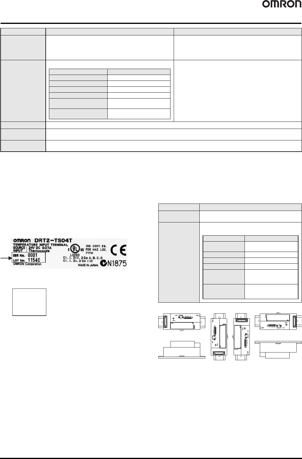
● Indicator accuracy when only the Unit or the Terminal Block is replaced
In the DRT2-TS04T, a cold junction compensator is included in the
Terminal Block. The indicator accuracy will be reduced depending on
the mounting direction if only the Terminal Unit is replaced and the
Lot No. and serial No. of the Terminal Block and Terminal Unit do not
match. The Lot No. and serial No. of the Terminal Block and Terminal
Unit can be found on the labels affixed to the products as shown
below.
Terminal Unit Label
Remove the terminal block. The label is affixed to the top of the unit.
Terminal Block Label
The label is affixed to the left side of the terminal block.
If the Lot No. and serial No. of the terminal block and Unit are the
same, basic performance specifications apply regardless of the
mounting direction. If the numbers are different, the following
indication accuracies apply.
Item Model DRT2-TS04T DRT2-TS04P *1
Input types
Switchable between R, S, K1, K2, J1, J2, T, B, L1, L2, E, U, N, W, and PLII
When set with Configurator:Input types can be set individually for each
input.
When set with DIP switch: The same input type setting applies to all 4
inputs.
Switchable between PT, JPT, PT2, and JPT2
When set with Configurator:Input types can be set individually for each
input.
When set with DIP switch: The same input type setting applies to all 4
inputs.
Indicator accuracy
(±0.3% of indication value or ±1°C, whichever is larger) ±1 digit max. *2
-200 to 850°C input range:
(±0.3% of indication value or ±0.8°C, whichever is larger) ±1 digit max.
-200 to 200°C input range:
(±0.3% of indication value or ±0.5°C, whichever is larger) ±1 digit max.
Conversion cycle 250 ms/4 points
Temperature
conversion data
Binary data (4-digit hexadecimal when normal display mode is selected or 8-digit hexadecimal when 1/100 display mode is selected.)
Insulation method
Between input and communication lines: Photocoupler insulation
Between temperature input signals: Photocoupler insulation
Input type Input accuracy
K1, K2, T, and N below -100°C ±2°C ±1 digit max.
U, L1, and L2 ±2°C ±1 digit max.
R and S below 200°C ±3°C ±1 digit max.
B below 400°C Not specified.
W
±0.3% of indication value or ±3°C
(whichever is larger) ±1 digit max.
PLII
±0.3% of indication value or ±2°C
(whichever is larger) ±1 digit max.
SER No.
0001
LOT No.
11540
Mounting direction Indication accuracies
Mounted normally
(1)
As specified in the Performance Specifications.
Mounted in any
other direction other
than (1)
(±0.3% of indication value or ±2°C, whichever is greater)
±1 digit max.
Input type Indication accuracies
K1, K2, T, and N
below -100°C
±3°C ±1 digit max.
U, L1, and L2 ±3°C ±1 digit max.
R and S below 200°C ±4°C ±1 digit max.
B below 400°C Not specified.
W
±0.3% of indication value or
±4°C (whichever is larger)
±1 digit max.
PLII
±0.3% of indication value or
±3°C (whichever is larger)
±1 digit max.
(1)
(2)
(3) (4) (5)
(6)
62 Temperature Input Terminals DRT2-TS04@
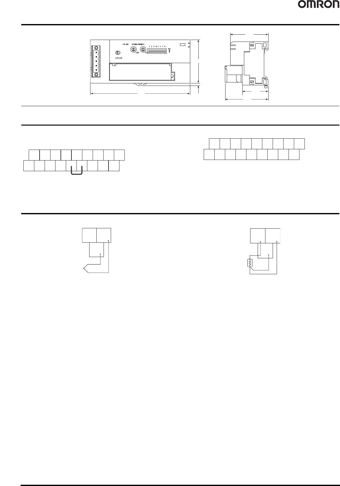
Dimensions (Unit: mm)
Terminal Arrangement
DRT2-TS04T DRT2-TS04P
Wiring Diagrams
DRT2-TS04T (Thermocouple input) DRT2-TS04P (Platinum resistance thermometer input)
3.1
115
50
49.7
29.9
43.9
DRT2-TS04T
DRT2-TS04P
NC
NC
NC
NC
NC
NC
NC
IN0
+
IN0
-
NC
IN1
+
IN1
-
IN2
+
IN2
-
IN3
+
IN3
-
Cold junction compensator
Do not touch or remove the cold junction compensator.
Otherwise temperature data will not display properly.
NC
NC
NC
NC
IN2
b
IN2
B
IN3
b
IN3
B
IN3
A
IN2
A
NC
NC
IN0
b
IN0
B
IN1
b
IN1
B
IN1
A
IN0
A
NC
IN0
+
IN0
-
IN0
b
IN0
B
IN0
A