drt2_devicenet_q102-e1_20_22_csm2147.pdf - 第38页
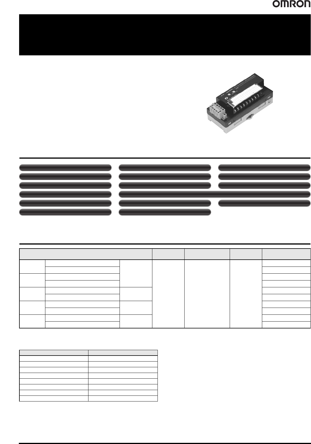
18 Transistor Remote I/O Te rminals DRT2- @ D08(-1)/ @ D16(-1) Transistor Remote I/O Terminals DRT2- @ D08(-1)/ @ D16(-1) Allows I/O Expansion with Transistor Terminals • Wide variety of data, such as mai ntenance system…
Smart Slaves DRT2 Series 17
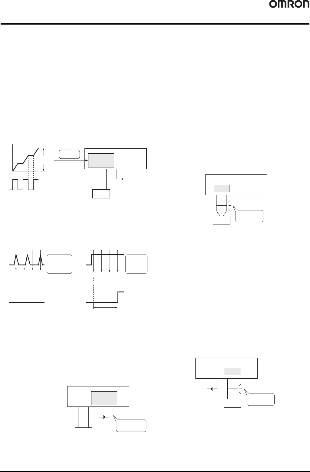
● Total ON Time Monitor Function
The total ON time for each I/O contact can be calculated (unit: s) and
recorded in the Slave. (The CX-Integrator or explicit messages can
be used to read the information.)
The monitor value can be set in the Slave, and when the set total
time is reached, a bit in the Status Area in the Unit will be turned ON.
(The CX-Integrator or explicit messages can be used to read the
details of the notification.)
• Counted time:0 to 4,294,967,295 seconds
(stored data: 0000 0000 to FFFF FFFF hex)
• Counting unit: One second
Note 1: The Contact Operation Counter and Total ON Time Monitor cannot be used
at the same time for the same contact. Select the function to be used under
the Detection Mode heading.
2: The Total ON Time Monitor operates only when the I/O power is ON.
3: The Total ON Time Monitor checks approximately every second whether the
connected devices are ON.
If the total ON time is calculated for ON times of less than a second, the
measurement may not be accurate.
● Input Filter Function
This function can read the input value several times within a preset
period and reduce the influence of incorrect signals due to switch
chattering or data corrupted by noise. The input filter function can
also be used for ON delay operation and OFF delay operation.
● Function to Prevent Incorrect Inputs Caused by Inrush
Current when Power Is Turned ON (input only)
The I/O power supply can be monitored to stop any input when the
I/O power is OFF and for 100 ms after it is turned ON. This function
reduces incorrect inputs caused by inrush current for 100ms after the
I/O power is turned ON.
● I/O Power Status Monitor Function
This function is used to detect whether the I/O power is ON.
When the I/O power supply
is turned OFF, a bit in the
Status Area in the Unit is
turned ON. (The
CX-Integrator or explicit
messages can be used to
read the content of the
notification.)
Note: The value for detecting a low
voltage for the I/O power
cannot be set.
● Sensor Power Short-circuit Detection Function (input
only)
The sensor power supply current can be monitored, and when the
current reaches or exceeds 100 mA per input contact, a sensor
power short-circuit is detected.
Check whether a sensor power short-circuit has been detected using
the indicators on the slave. When a sensor power short-circuit is
detected, a bit in the Status Area in the Unit will turn ON. (The
CX-Integrator or explicit messages can be used to read the details of
the notification.) The sensor will automatically recover when the
cause of the short-circuit is removed, and the power output to the
connector where the short-circuit was detected will turn ON.
Note: Use a Power Supply Unit with a rated power supply of 50 W or higher for the
communications power supply. A short-circuit is detected when the Unit's
sensor power output current reaches or exceeds 100 mA per input connector.
When a short-circuit occurs, the communications power supply may be
temporarily interrupted. After a short-circuit has been detected, the power will
be automatically restored, but during the power interruption use an external
circuit in the configuration to make sure the system is operating safely.
Use the following equations to calculate the sensor's current consumption.
• Total network current = Total Unit current consumption + Total sensor
current consumption
• Communications power supply capacity (Total network current +
Short-circuit detection current) x (=100 mA) x (DeviceNet network voltage)
●
External Load Short-circuit Detection Function (output only)
The load current of the Output Unit can be monitored, and an
external load short-circuit can be detected when the current exceeds
a set value per contact (or per common). When an external load
short-circuit is detected, the output is turned OFF to prevent damage
to the Unit's output circuit. The LED indicators on the Slave Unit can
be used to check which contact has been detected as having an
external load short-circuit. When an external load short-circuit is
detected, a bit in the Status Area in the Unit will turn ON. (The
CX-Integrator or explicit messages can be used to read the details of
the notification.)
Manual recovery is the only way to remove the cause of the
short-circuit.
Note: The OMRON S8@@ Power Supply Unit is recommended for the I/O power
supply.
If a Power Supply Unit with a dropping overcurrent protection characteristic is
used, the load short-circuit may not be detected. Always use a Power Supply
Unit with a rating of 100 W or higher if it uses a dropping overcurrent protection
characteristic.
ON
OFF
Slave
To ta l
ON time
Connected device
I/O power supply
Sensor
Total
ON time
Stored in
Slave
ON
ON
1234
OFF
Data input
ON
OFF
OFF OFF ON
ON
ON
1234
OFF
Data input
ON delay time
(Equal to the input filter time.)
ON
OFF
ON ON ON
The signal is
considered OFF
because all four
readings were
not ON.
The signal is
considered ON
because all
four readings
were ON.
Slave
I/O
power voltage
I/O power
Sensor
Monitors whether
I/O power is ON.
Slave
Has the sensor
power shorted?
Sensor
Short-circuit
Slave
External load
Output forced OFF
Short-circuit
Has the external
load shorted?
18 Transistor Remote I/O Terminals DRT2-@D08(-1)/@D16(-1)
Transistor Remote I/O Terminals
DRT2-
@
D08(-1)/@D16(-1)
Allows I/O Expansion with
Transistor Terminals
• Wide variety of data, such as maintenance system data, can be collected
without affecting the productivity of the control system.
• Valuable information can be collected and managed through the
network, including information on the communications power supply
voltage levels, Unit wear and tear, and equipment operating information.
• Expansion via Expansion I/O Units
• With no communications baud rate settings required and detachable
terminal blocks, maintenance is easier.
Smart Slave Functions
*1. The operation time monitor cannot be used with the DRT2-@D08(-1).
*2. Expansion Units cannot be added with the DRT2-@D08(-1)or DRT2-MD16(-1).
Ordering Information
Expansion Units
One Expansion Unit can be added to each DRT2-ID16(-1)/-OD16(-1) or DRT2-ROS16 I/O Slave.
The following Expansion Units are available to enable flexible expansion with combinations for the required number of points.
Specifications I/O connections
Rated internal circuit
power supply voltage
Rated I/O power
supply voltage
Model
Inputs
NPN (+ common)
16 points
M3
Screw terminals
Supplied from the
communications
connector
24 VDC
DRT2-ID16
PNP (- common) DRT2-ID16-1
Outputs
NPN (- common) DRT2-OD16
PNP (+ common) DRT2-OD16-1
I/O
NPN (input: + common, output: - common)
Input: 8 points/
Output: 8 points
DRT2-MD16
PNP (input: - common, output: + common) DRT2-MD16-1
Inputs
NPN (+ common)
8 points
DRT2-ID08
PNP (- common) DRT2-ID08-1
Outputs
NPN (- common)
8 points
DRT2-OD08
PNP (+ common) DRT2-OD08-1
Model Number of I/O points
XWT-ID08 8-point inputs (NPN)
XWT-ID08-1 8-point inputs (PNP)
XWT-OD08 8-point outputs (NPN)
XWT-OD08-1 8-point outputs (PNP)
XWT-ID16 16-point inputs (NPN)
XWT-ID16-1 16-point inputs (PNP)
XWT-OD16 16-point outputs (NPN)
XWT-OD16-1 16-point outputs (PNP)
Power-ON inrush current protection (input or I/O only)
Operation time monitor (input and output only) *1
Contact operation counter Unit conduction time monitor
Total ON time monitor Unit comments Connected device comments
Network power supply voltage monitor I/O power supply monitor function Communications error log monitor
Input filter (input or I/O only)
Removable terminal block Communications speed auto-detection No need to wire Unit power supply
Expansion via Expansion I/O Units *2 Last maintenance date
Transistor Remote I/O Terminals DRT2-@D08(-1)/@D16(-1) 19
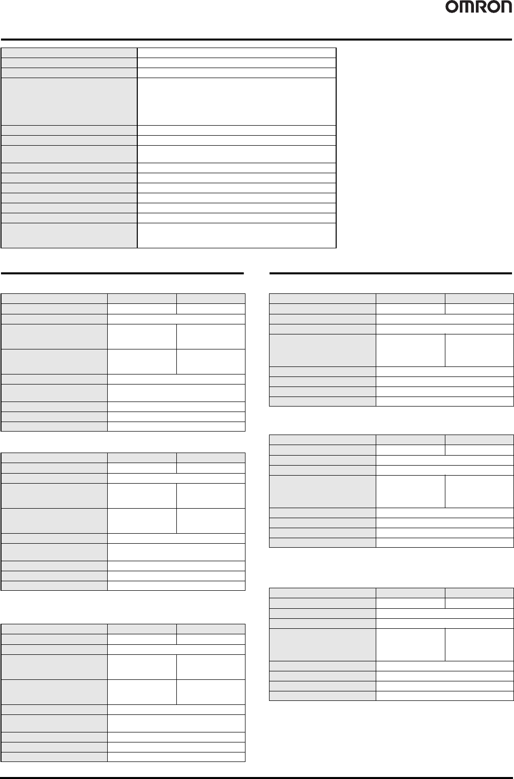
General Specifications
Input Specifications
● 8-point Inputs Terminals with Transistors
● 16-point Inputs Terminals with Transistors
● 8-point Inputs/8-point Outputs Terminals with
Transistors
Output Specifications
● 8-point Outputs Terminals with Transistors
● 16-point Outputs Terminals with Transistors
● 8-point Inputs/8-point Outputs Terminals with
Transistors
Communications power supply voltage 11 to 25 VDC
Unit power supply voltage Not required (Supplied from the communications connector.)
I/O power supply voltage 20.4 to 26.4 VDC (24 VDC -15%/+10%)
Communications power supply current
consumption
DRT2-ID08(-1) : 40 mA max. (24 VDC), 70 mA max. (11 VDC)
DRT2-OD08 : 40 mA max. (24 VDC), 60 mA max. (11 VDC)
DRT2-OD08-1 : 35 mA max. (24 VDC), 55 mA max. (11 VDC)
DRT2-ID16(-1) : 40 mA max. (24 VDC), 65 mA max. (11 VDC)
DRT2-OD16(-1) : 35 mA max. (24 VDC), 60 mA max. (11 VDC)
DRT2-MD16(-1) : 40 mA max. (24 VDC), 65 mA max. (11 VDC)
Dielectric strength 500 VAC (between isolated circuits)
Noise immunity Conforms to IEC61000-4-4, 2 kV (power line)
Vibration resistance
10 to 60 Hz, 0.7-mm double amplitude, 60 to 150 Hz, 50 m/s
2
for
80 min each in the X, Y, and Z directions
Shock resistance 150m/s
2
, 6 directions, 3 times each
Mounting method DIN 35 mm-track mounting
Screw tightening torque M3 (power, I/O terminal): 0.5 N·m
Ambient operating temperature –10°C to 55°C
Ambient operating humidity 25 to 85% (with no condensation)
Ambient storage temperature -25°C to 65°C
Weight
DRT2-ID08(-1)/OD08(-1) : 135 g max.
DRT2-MD16(-1) : 145 g max.
DRT2-ID16(-1)/OD16(-1) : 140 g max.
Item Model DRT2-ID08 DRT2-ID08-1
Internal I/O common NPN PNP
Number of I/O points 8 inputs
ON voltage
15 VDC min.
(between each input
terminal and V)
15 VDC min.
(between each input
terminal and G)
OFF voltage
5 VDC max.
(between each input
terminal and V)
5 VDC min.
(between each input
terminal and G)
OFF current 1.0 mA max.
Input current
6.0 mA max. per point at 24 VDC
3.0 mA max. per point at 17 VDC
ON delay time 1.5 ms max.
OFF delay time 1.5 ms max.
Number of points per common 8 per common
Item Model DRT2-ID16 DRT2-ID16-1
Internal I/O common NPN PNP
Number of I/O points 16 inputs
ON voltage
15 VDC min.
(between each input
terminal and V)
15 VDC min.
(between each input
terminal and G)
OFF voltage
5 VDC max.
(between each input
terminal and V)
5 VDC min.
(between each input
terminal and G)
OFF current 1.0 mA max.
Input current
6.0 mA max. per point at 24 VDC
3.0 mA max. per point at 17 VDC
ON delay time 1.5 ms max.
OFF delay time 1.5 ms max.
Number of points per common 16 per common
Item Model DRT2-MD16 DRT2-MD16-1
Internal I/O common NPN PNP
Number of I/O points 8 inputs
ON voltage
15 VDC min.
(between each input
terminal and V)
15 VDC min.
(between each input
terminal and G)
OFF voltage
5 VDC max.
(between each input
terminal and V)
5 VDC min.
(between each input
terminal and G)
OFF current 1.0 mA max.
Input current
6.0 mA max. per point at 24 VDC
3.0 mA max. per point at 17 VDC
ON delay time 1.5 ms max.
OFF delay time 1.5 ms max.
Number of points per common 8 per common
Item Model DRT2-OD08 DRT2-OD08-1
Internal I/O common NPN PNP
Number of I/O points 8 outputs
Rated output current 0.5 A per point, 4 A per common
Residual voltage
1.2 V max.
(0.5 A DC between
each output terminal
and G)
1.2 V max.
(0.5 A DC between
each output terminal
and V)
Leakage current 0.1 ms max.
ON delay time 0.5 ms max.
OFF delay time 1.5 ms max.
Number of points per common 8 per common
Item Model DRT2-OD16 DRT2-OD16-1
Internal I/O common NPN PNP
Number of I/O points 16 outputs
Rated output current 0.5 A per point, 4 A per common
Residual voltage
1.2 V max.
(0.5 A DC between
each output terminal
and G)
1.2 V max.
(0.5 A DC between
each output terminal
and V)
Leakage current 0.1 ms max.
ON delay time 0.5 ms max.
OFF delay time 1.5 ms max.
Number of points per common 16 per common
Item Model DRT2-MD16 DRT2-MD16-1
Internal I/O common NPN PNP
Number of I/O points 8 outputs
Rated output current 0.5 A per point, 4 A per common
Residual voltage
1.2 V max.
(0.5 A DC between
each output terminal
and G)
1.2 V max.
(0.5 A DC between
each output terminal
and V)
Leakage current 0.1 ms max.
ON delay time 0.5 ms max.
OFF delay time 1.5 ms max.
Number of points per common 8 per common