IPC-TM-650 EN 2022 试验方法--.pdf - 第112页
Main image (Height) S-L surface Material ratio curve Angular spectrum Autocorrelation function 2.66um Number 2.2.22 Subject Noncontact Metallic Foil Surface Topography/Texture Date 5/20 Revision Page 5 of 5 IPC-TM-650 ― …
F-Operation
• A filter for removing surface shapes (i.e., Plane tilt, curved
surface).
• Insures that the geometry of the sample surface does not
affect the magnitude of the measured roughness value.
• Eliminates the user from having to place the sample per-
fectly flat during the scan.
L-Filter
• Commonly known as a high-pass filter.
• This filter is equivalent to λc for line roughness defined by
ISO 4287.
• Removes waviness and other nonuniform surface shapes to
extract surface roughness data (normalization filter).
A.2.2
As described in Section V, the proper filter values that
properly align with the ISO 25178 for this specific procedure
(50X objective with 0.95 NA, 200 µm X 1000 µm scanned
area) are:
• S-filter: 2 µm
• F-operation: Plane Correction
• L-filter: 0.2 mm
A.3 Sample Measurements Examples
A.3.1
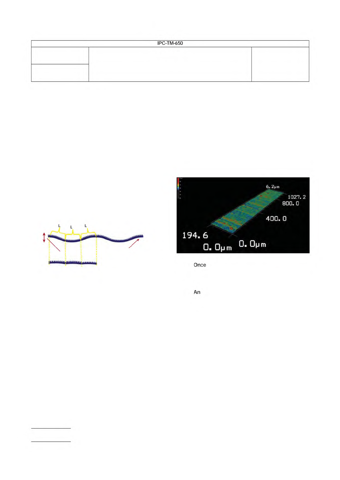
Shown below are examples of what the user should
expect from a successful analysis with a 3-D measurement
tool. The first picture shows a qualitative 3-D rendering of the
metallic foil surface from a laser confocal microscope tool.
A.3.2
A laser confocal microscope, or similar noncontact
3-D surface measurement tool should be able to provide
enough resolution in both the XY and Z direction to provide an
accurate representation of the material.
A.3.3
the 3-D model is obtained, the surface will then
be quantified using the ISO 25178 Surface Roughness mod-
ule.
A.3.4
example of how the data could be outputted is
shown below. Other similar forms of data outputs would be
provided to the user by other noncontact 3-D measurement
tools.
Surface roughness
Surface waviness
Number
2.2.22
Subject
Noncontact Metallic Foil Surface Topography/Texture
Date
5/20
Revision
Page 4 of 5
IPC-TM-650
—
a
6・
2pm
墓
1027.
2
800.
0
400.0
194.
6
0.
0pm
口
Once
An
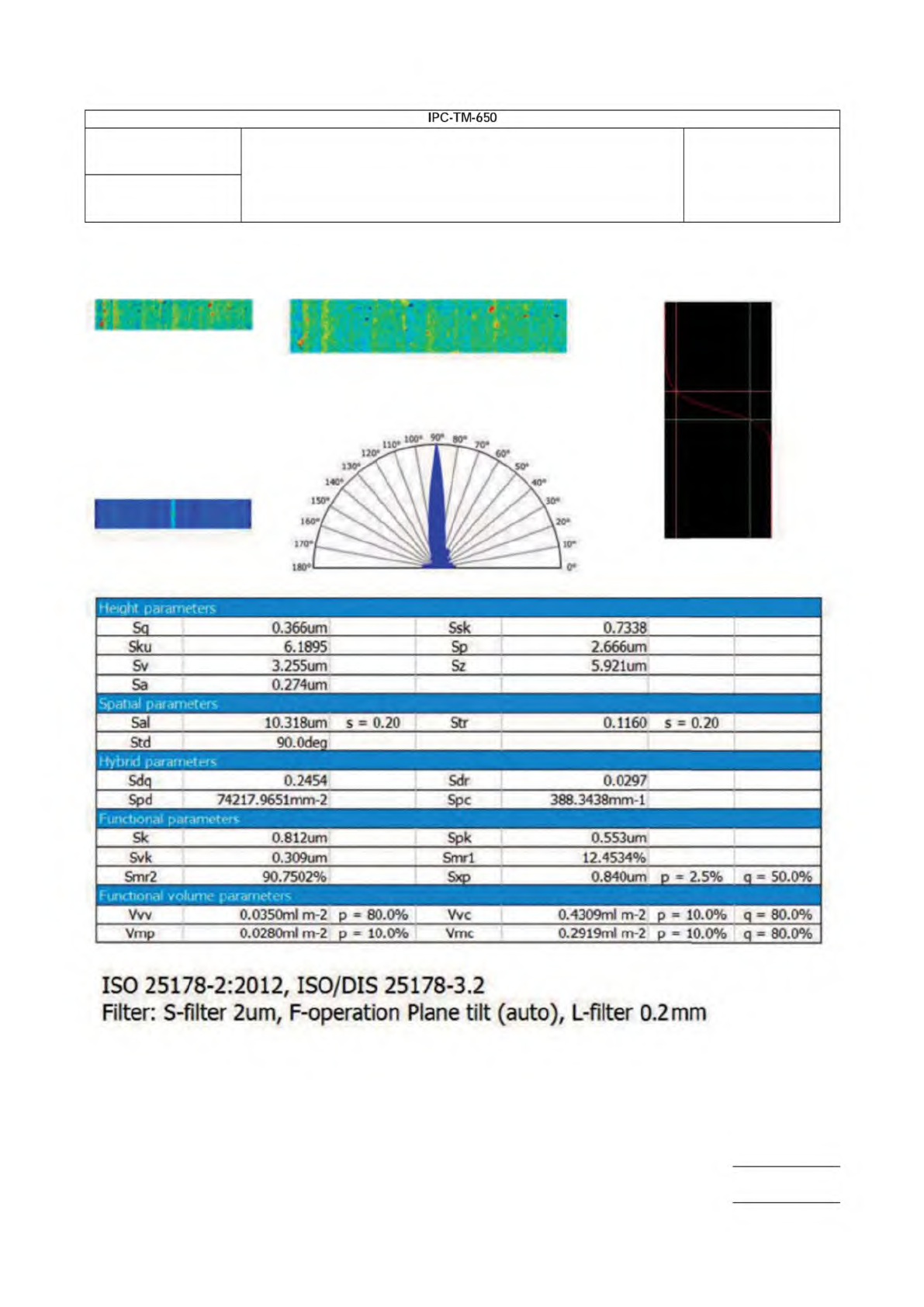
Main image (Height) S-L surface Material ratio curve
Angular spectrum
Autocorrelation function
2.66um
Number
2.2.22
Subject
Noncontact Metallic Foil Surface Topography/Texture
Date
5/20
Revision
Page 5 of 5
IPC-TM-650
―
|
Height
parameters
i
Sq
0.366um
Ssk
0.7338
Sku
6.1895
Sp
2.666um
Sv
3
・255um
Sz
5.921um
Sa
0.274um
Spatial
parameters
Sal
10.318um
s
=
0.20
Str
0.1160
s
=
0.20
Std
90.0deg
Hyt)rd
parameters
Sdq
0.2454
Sdr
0.0297
Spd
74217.9651mm-2
Spc
388.3438mm-l
1
Funcbonai
parameters
Sk
0.812um
Spk
0.553um
Svk
0.309um
Smrl
12.4534%
Smr2
90.7502%
Sxp
0.840um
p
=
25%
q
=
50.0%
Funcbonal
volume
parameters
Vw
0.0350ml
m-2
p
=
80.0%
Vvc
0.4309ml
m-2
p
=
10.0%
q
=
80.0%
Vmp
0.0280ml
m-2
p
=
10.0%
Vmc
0.2919ml
m-2
p
=
10.0%
q
=
80.0%
ISO
25178-2:2012,
ISO/DIS
25178-3.2
Filter:
S-filter
2um,
F-operation
Plane
tilt
(auto),
L-filter
0.2mm
MIL-STD-105
MIL-P-13949
The Institute for Interconnecting and Packaging Electronic Circuits
2215 Sanders Road • Northbrook, IL 60062-6135
Material in this Test Methods Manual was voluntarily established by Technical Committees of the IPC. This material is advisory only
and its use or adaptation is entirely voluntary. IPC disclaims all liability of any kind as to the use, application, or adaptation of this
material. Users are also wholly responsible for protecting themselves against all claims or liabilities for patent infringement.
Equipment referenced is for the convenience of the user and does not imply endorsement by the IPC.
Page 1 of 2
IPC-TM-650
TEST
METHODS
MANUAL
1
Scope
This
test
method
covers
acceptance
of
incoming
copper
clad
epoxy-glass
laminates
ranging
in
thickness
from
0.8
mm
to
6.5
mm,
clad
on
one
or
both
sides.
It
provides
for
a
standard
method
of
inspection
and
establishes
operations
that
simulate
the
manufacture
of
PWBs.
Specific
values
for
the
acceptability
are
based
on
copper
foil
adhesion
and
visual
surface
condition
of
the
base
laminate.
2
Applicable
Documents
Sampling
Procedures
and
Tables
for
Inspec¬
tion
by
Attributes
Plastic
Sheet,
Laminated,
Copper-Clad
(For
Printed
Wiring)
3
Test
Specimen
3.1
Specimen
One
specimen
shall
be
tested
for
each
sample,
except
in
the
case
where
material
is
clad
on
both
sides,
in
which
case
two
specimens
shall
be
processed
for
each
sample
(one
for
each
surface).
Each
specimen
will
have
four
readings.
3.2
Sampling
The
sampling
procedure
will
be
to
MIL-STD-
105.
The
inspection
level
shall
be
S-2
at
6.5
A.Q.L
4
Apparatus
4.1
Complete
photo
processing
facilities
4.2
Etching
facilities
5
Procedures
5.1
Print
and
Etch
For
print
and
etch
testing
use
5.3.1,
5.3.2, 5.3.4,
5.3.5, 5.3.7,
5.3.8,
5.3.9,
5.3.10,
and
5.3.1
1
only.
5.2
Print,
Etch,
and
Plate
For
print,
etch,
and
plate
test¬
ing,
use
5.3.1
through
5.3.1
1
inclusively.
5.3
Steps
Number
2.3.1
Subject
Chemical
Processing,
Suitable
Processing
Material
Date
Revision
4/73
Originating
Task
Group
N/A
5.3.1.
1
Sand
the
edges
of
the
test
specimens
to
remove
burrs,
allowing
close
contact
between
the
specimen,
nega¬
tive,
and
frame
glass,
residing
in
a
better
defined
etched
pat¬
tern.
5.3.1.
2
Scrub
the
copper
surface(s)
with
FFF
pumice
and
brush
to
remove
any
contamination
on
the
surface
of
the
specimen
until
it
passes
a
water
break
test.
5.3.1.
3
Dry
using
compressed
filtered
air.
5.3.2
Apply
Resist
5.3.2.1
Dip
the
specimens
in
the
following
photo-resist
solu¬
tion:
•
One
part
KPR
III
•
One
part
Toluene
•
One
part
Acetone
All
parts
are
by
volume
and
should
be
used
at
room
tempera¬
ture.
Specific
gravity
of
the
solution
is
0.920.
5.3.2.2
Hold
the
specimen
by
one
corner
when
dipping.
Allow
excess
solution
to
drain
until
dripping
stops.
5.3.2.3
Put
the
specimens
on
the
rack
(after
draining)
into
80℃
oven
for
three
to
five
minutes
to
dry
and
harden
KPR.
5.3.2.4
Remove
the
rack
from
the
oven
and
allow
the
speci¬
mens
to
cool
to
room
temperature.
5.3.2.S
Place
the
specimens
upon
the
negative
in
the
print¬
ing
frame
with
the
copper
side
against
the
negative.
5.3.2.6
Expose
the
mounted
specimen
for
seven
minutes,
75
mm
from
the
fluorescent
black
light.
S.3.2.7
Develop
in
trichlorethylene
vapor
for
1
5
seconds.
It
may
require
two
to
six
cycles
until
the
pattern
is
clear.
Air
dry
the
specimen
after
developing.
5.3.2.8
Use
artwork
from
MIL-P-13949.
5.3.1
Preparation
5.3.3
Etch
per
MIL-P-13949,
Method
A
or
B