IPC-TM-650 EN 2022 试验方法--.pdf - 第791页
Figure 1 Right Angle Connector Fixture (Suggested) IPC-TM-650 Page 2 of 5 Number 3.8 Subject Mechanical Shock, Connectors Date 7/75 Revision A IPC-3-8-1 4.3 A circuit monitor capable of supplying a continuous cur¬ rent o…

Material in this Test Methods Manual was voluntarily established by Technical Committees of the IPC. This material is advisory only
and its use or adaptation is entirely voluntary. IPC disclaims all liability of any kind as to the use, application, or adaptation of this
material. Users are also wholly responsible for protecting themselves against all claims or liabilities for patent infringement.
Equipment referenced is for the convenience of the user and does not imply endorsement by the IPC.
Page 1 of 5
r
ASSOCIATION
CONNECTING
/
ELECTRONICS
INDUSTRIES
2215
Sanders
Road
Northbrook,
IL
60062-6135
IPC-TM-650
TEST
METHODS
MANUAL
1
.0
Scope
1
.1
To
determine
the
effect
on
the
connector
of
the
stresses
produced
by
transient
acceleration
or
deceleration
forces
resulting
from
handing,
transportation,
or
field
operation.
2
.0
Reference
Documents
2.1
Information
in
this
section
is
intended
to
parallel
the
test
method
described
in
EIA-RS-364/TP-27.
3
.0
Test
Specimen
3.1
A
connector
(plug
and
receptacle)
complete
with
appli¬
cable
guide,
keying,
and
engaging
hardware
or
a
card-
edge
receptacle
and
mating
nominal-thickness
printed
circuit
board.
3.2
Mounting
and
Termination
3.2.1
Right
Angle,
Two-Piece
Connector
The
receptacle
shall
be
mounted
and
terminated
normally
during
this
test;
receptacles
designed
for
mounting
on
non-rigid
bases
(e.g.,
motherboards,
metal-plate
back
panels,
etc.)
shall
be
mounted
on
the
smallest
section
of
such
a
base
that
will
accommodate
the
test
specimen.
The
plug
shall
be
termi¬
nated
normally
during
the
test
and
shall
be
mounted
on
a
nominal-thickness
printed
circuit
board
extending
the
full
width
of
the
plug;
the
board
shall
extend
a
minimum
of
four
inches
from
the
receptacle
when
the
connector
is
mated.
3.2.2
Card-Edge
Receptacle
The
receptacle
shall
be
mounted
and
terminated
normally
during
this
test
(see
3.2.1).
The
mating
printed
circuit
board
shall
extend
the
full
width
of
the
receptacle
and
shall
extend
a
minimum
of
four
inches
from
the
receptacle
when
mated.
3.2.3
Parallel,
Two-Piece
Connector
The
receptacle
and
plug
shall
be
terminated
normally
during
this
test;
both
com¬
ponents
shall
be
mounted
on
nominal-thickness
printed
circuit
boards
extending
the
full
width
of
each.
The
printed
circuit
boards
shall
extend
a
minimum
of
four
inches
from
each
com¬
ponent
when
the
connector
is
mated.
Number
3.8
Subject
Mechanical
Shock,
Connectors
Date
Revision
7/75
A
Originating
Task
Group
N/A
3.3
Fixturing
3.3.1
Right
Angle
Connector
The
test
specimen
shall
be
held
in
an
adequate
resonant
free
fixture.
(Figure
1
,
Reference
Example.)
3.3.2
Parallel
Connector
The
test
specimen
shall
be
held
in
an
adequate
resonant
free
fixture.
(Figure
2,
Reference
Example.)
3.4
The
connector
shall
be
wire
(or
printed
circuit
boards)
designed
such
that
a
continuous
electrical
circuit
(comprising
all
contacts
in
series)
is
formed
when
the
plug
(or
board)
and
receptacle
are
mated.
4.0
Apparatus
4.1
A
shock
machine
capable
of
producing
the
specified
input
shock
pulse
as
shown
in
Figures
3
and
4.
The
machine
may
be
of
a
free-
or
accelerated-fall,
resilient
rebound,
non-
resilient,
hydraulic
or
pneumatic
actuated,
or
other
type.
4.2
A
shock
measurement
system
consisting
of
an
accelera¬
tion
sensitive
transducer
(accelerometer)
and
appropriate
impedance
matching,
amplifying
and
recording
instrumenta¬
tion.
The
entire
system
shall
exhibit
a
frequency
response
within
the
limits
shown
in
Figure
5.
4.2.1
A
piezoelectric
accelerometer
used
as
the
transducer
shall
have
a
minimum
fundamental
resonant
frequency
of
14
KHz
(a
resonant
frequency
>30
KHz
is
recommended).
For
suitable
low
frequency
response,
the
RC
time
constant
of
the
accelerometer
and
its
load
shall
be
RC
>0.2
where:
R
-
load
resistance
(ohms)
C
-
accelerometer
capacitance,
plus
shunt
capacitance
of
the
load
and
the
inter-connecting
cable
(farads)
4.2.2
A
strain
gage
accelerometer
used
as
the
transducer
shall
have
a
minimum
undamped
natural
frequency
>1500
Hz,
with
damping
from
0.64
to
0.70
of
critical.
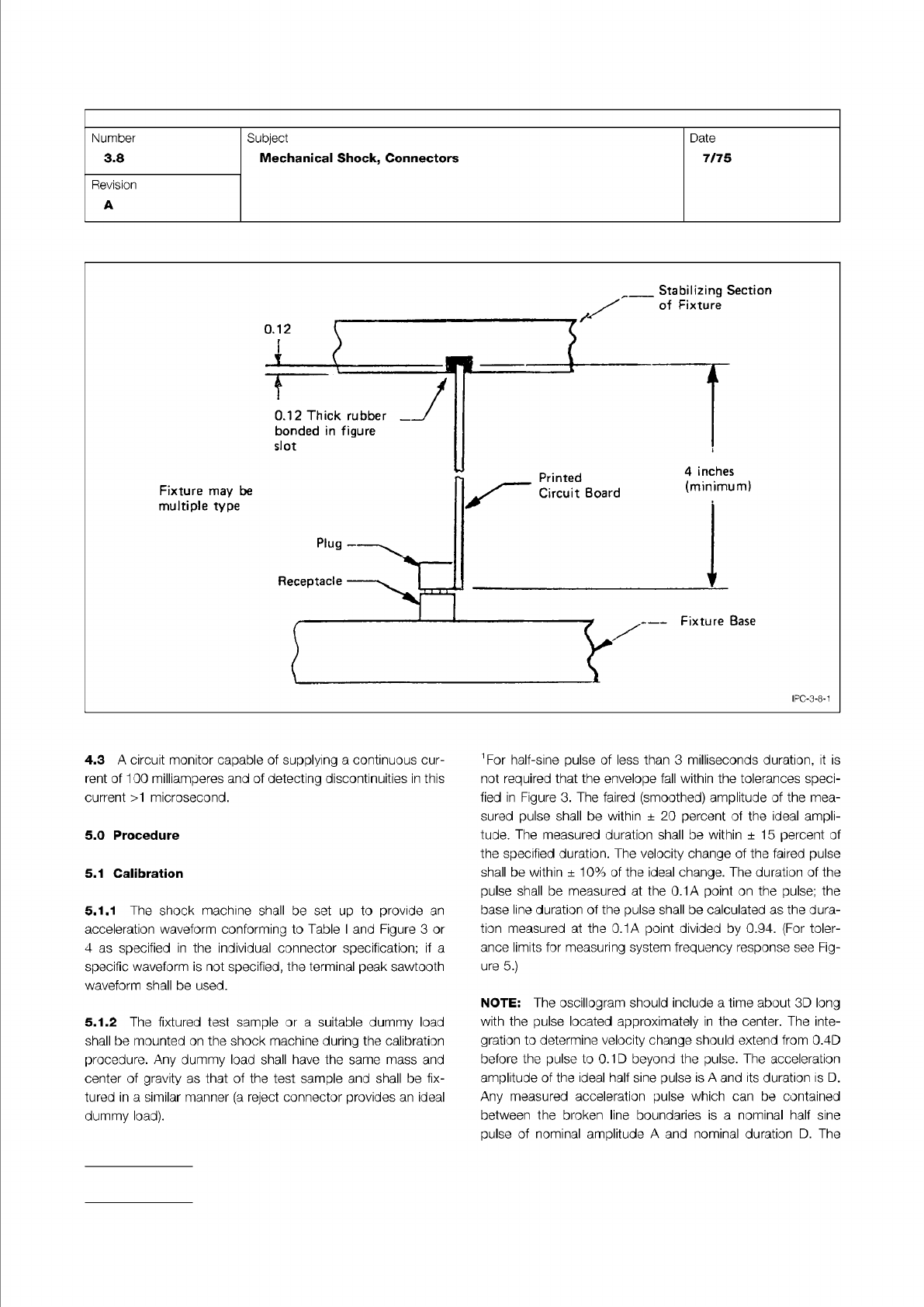
Figure 1 Right Angle Connector Fixture (Suggested)
IPC-TM-650
Page 2 of 5
Number
3.8
Subject
Mechanical
Shock,
Connectors
Date
7/75
Revision
A
IPC-3-8-1
4.3
A
circuit
monitor
capable
of
supplying
a
continuous
cur¬
rent
of
100
milliamperes
and
of
detecting
discontinuities
in
this
current
>1
microsecond.
5.0
Procedure
5.1
Calibration
5.1.1
The
shock
machine
shall
be
set
up
to
provide
an
acceleration
waveform
conforming
to
Table
I
and
Figure
3
or
4
as
specified
in
the
individual
connector
specification;
if
a
specific
waveform
is
not
specified,
the
terminal
peak
sawtooth
waveform
shall
be
used.
5.1.2
The
fixtured
test
sample
or
a
suitable
dummy
load
shall
be
mounted
on
the
shock
machine
during
the
calibration
procedure.
Any
dummy
load
shall
have
the
same
mass
and
center
of
gravity
as
that
of
the
test
sample
and
shall
be
fix¬
tured
in
a
similar
manner
(a
reject
connector
provides
an
ideal
dummy
load).
〔
For
half-sine
pulse
of
less
than
3
milliseconds
duration,
it
is
not
required
that
the
envelope
fall
within
the
tolerances
speci¬
fied
in
Figure
3.
The
faired
(smoothed)
amplitude
of
the
mea¬
sured
pulse
shall
be
within
土
20
percent
of
the
ideal
ampli¬
tude.
The
measured
duration
shall
be
within
±
15
percent
of
the
specified
duration.
The
velocity
change
of
the
faired
pulse
shall
be
within
±
10%
of
the
ideal
change.
The
duration
of
the
pulse
shall
be
measured
at
the
0.1A
point
on
the
pulse;
the
base
line
duration
of
the
pulse
shall
be
calculated
as
the
dura¬
tion
measured
at
the
0.1A
point
divided
by
0.94.
(For
toler¬
ance
limits
for
measuring
system
frequency
response
see
Fig¬
ure
5.)
NOTE:
The
oscillogram
should
include
a
time
about
3D
long
with
the
pulse
located
approximately
in
the
center.
The
inte¬
gration
to
determine
velocity
change
should
extend
from
0.4D
before
the
pulse
to
0.1
D
beyond
the
pulse.
The
acceleration
amplitude
of
the
ideal
half
sine
pulse
is
A
and
its
duration
is
D.
Any
measured
acceleration
pulse
which
can
be
contained
between
the
broken
line
boundaries
is
a
nominal
half
sine
pulse
of
nominal
amplitude
A
and
nominal
duration
D.
The
NOTE:
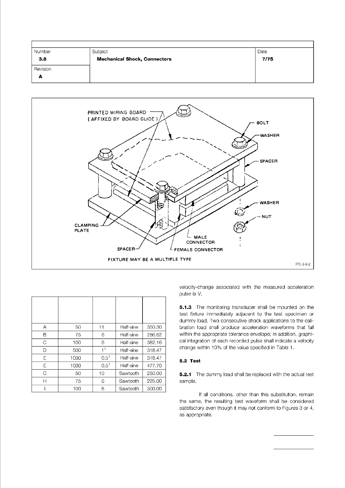
Figure 2 Parallel Connector Fixture (Suggested)
Table I
Test Conditions
Test
Condition
Peak
Acceleration
A-Gravity
Units
Nominal
Duration
D-Milli-
seconds Waveform
Velocity
Change
Vi
(G-MS)
IPC-TM-650
Page 3 of 5
Number
3.8
Subject
Mechanical
Shock,
Connectors
Date
7/75
Revision
A
FIXTURE
MAY
BE
A
MULTIPLE
TYPE
IPC-3-8-2
A
50
11
Half-sine
350.30
B
75
6
Half-sine
286.62
C
100
6
Half-sine
382.16
D
500
11
Half-sine
318.47
E
1000
0.51
Half-sine
318.47
F
5000
0.51
Half-sine
477.70
G
50
10
Sawtooth
250.00
H
75
6
Sawtooth
225.00
I
100
6
Sawtooth
300.00
velocity-change
associated
with
the
measured
acceleration
pulse
is
V.
5.1.3
The
monitoring
transducer
shall
be
mounted
on
the
test
fixture
immediately
adjacent
to
the
test
specimen
or
dummy
load.
Two
consecutive
shock
applications
to
the
cali¬
bration
load
shall
produce
acceleration
waveforms
that
fall
within
the
appropriate
tolerance
envelope;
in
addition,
graphi¬
cal
integration
of
each
recorded
pulse
shall
indicate
a
velocity
change
within
10%
of
the
value
specified
in
Table
1
.
5.2
Test
5.2.1
The
dummy
load
shall
be
replaced
with
the
actual
test
sample.
If
all
conditions,
other
than
this
substitution,
remain
the
same,
the
resulting
test
waveform
shall
be
considered
satisfactory
even
though
it
may
not
conform
to
Figures
3
or
4,
as
appropriate.