IPC-TM-650 EN 2022 试验方法--.pdf - 第596页
ASTM-D-257 Figure 1 V olume and Surface Re sistivity T e st Pattern . (Side 1) Figure 2 V olume and Surface Re sistivity T e st Pattern . (Side 2) The Institute for Int erconnecting and Packaging E lectronic Circuits 221…
minor
major
IPC-TM-650
Page 3 of 3
Number
2.6.15
Subject
Corrosion,
Flux
Date
06/04
Revision
C
held
for
30
minutes.
The
humidity
should
then
be
increased
to
93%RH.
5.6.3.3
Expose
specimen
to
the
above
environment
for
240
hours
(10
days).
M
and
H
fluxes
may
be
tested
in
the
cleaned,
as
well
as
uncleaned,
condition.
Specimens
shall
be
cleaned
per
the
manufacturers
instructions.
5.7
Evaluation
5.7.1
After
the
exposure
period,
remove
test
specimens
from
humidity
chamber,
examine
at
20X
magnification
and
compare
with
observations
noted
in
6.5
(see
8.2).
5.7.2
For
purposes
of
this
test
method,
the
following
defini¬
tion
of
corrosion
shall
prevail:
"A
chemical
reaction
between
the
copper,
the
solder,
and
the
constituents
of
the
flux
resi¬
dues,
which
occurs
after
soldering
and
during
exposure
to
the
above
environmental
conditions.*
*
Corrosion
for
this
test
is
classified
as
follows:
5.7.2.1
Minor
Corrosion
Any
initial
change
of
color,
which
may
develop
when
the
test
panel
is
heated
during
soldering,
is
disregarded.
Discrete
white
or
colored
spots
in
the
flux
resi¬
dues
or
a
color
change
to
green-blue
without
pitting
of
the
copper
or
formation
of
excrescences
is
regarded
as
corrosion.
5.7.2.2
Major
Corrosion
Any
initial
change
of
color
which
may
develop
when
the
test
panel
is
heated
during
soldering
is
disregarded.
Subsequent
development
of
green-blue
discol¬
oration
with
observation
of
pitting
of
the
copper
panel
or
excrescences
at
the
interfaces
of
the
flux
residue
and
copper
boundary,
is
regarded
as
corrosion.
6
Notes
6・1
Questionable
results
may
be
confirmed
by
analyzing
the
suspected
corrosion
via
Energy
Dispersive
X-ray
Spectros¬
copy
(EDS)
for
the
presence
of
copper.
6.2
Color
photos
before
and
after
the
test
are
valuable
tools
in
identifying
and
documenting
corrosion.
6.3
Safety
Observe
all
appropriate
precautions
on
MSDS
for
chemicals
involved
in
this
test
method.
ASTM-D-257
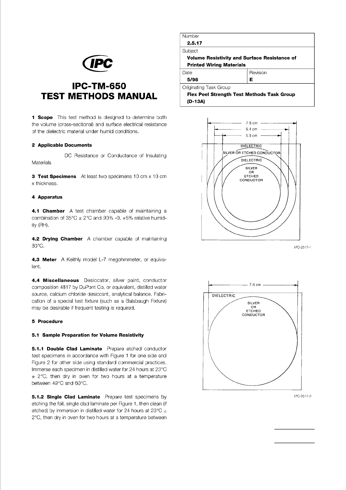
Figure 1 Volume and Surface Resistivity Test Pattern.
(Side 1)
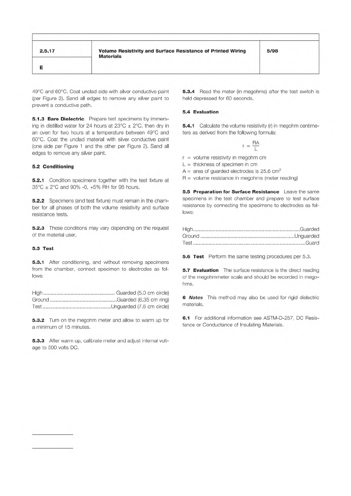
Figure 2 Volume and Surface Resistivity Test Pattern.
(Side 2)
The Institute for Interconnecting and Packaging Electronic Circuits
2215 Sanders Road • Northbrook, IL 60062
Material in this Test Methods Manual was voluntarily established by Technical Committees of the IPC. This material is advisory only
and its use or adaptation is entirely voluntary. IPC disclaims all liability of any kind as to the use, application, or adaptation of this
material. Users are also wholly responsible for protecting themselves against all claims or liabilities for patent infringement.
Equipment referenced is for the convenience of the user and does not imply endorsement by the IPC.
Page 1 of 2
IPC-TM-650
TEST
METHODS
MANUAL
1
Scope
This
test
method
is
designed
to
determine
both
the
volume
(cross-sectional)
and
surface
electrical
resistance
of
the
dielectric
material
under
humid
conditions.
2
Applicable
Documents
DC
Resistance
or
Conductance
of
Insulating
Materials
3
Test
Specimens
At
least
two
specimens
10
cm
x
10
cm
x
thickness.
4
Apparatus
4.1
Chamber
A
test
chamber
capable
of
maintaining
a
combination
of
35℃
±
2
℃
and
90%
-0,
+5%
relative
humid¬
ity
(RH).
4.2
Drying
Chamber
A
chamber
capable
of
maintaining
80℃.
4.3
Meter
A
Keithly
model
L-7
megohmmeter,
or
equiva¬
lent.
4.4
Miscellaneous
Desiccator,
silver
paint,
conductor
composition
4817
by
DuPont
Co.
or
equivalent,
distilled
water
source,
calcium
chloride
desiccant,
analytical
balance.
Fabri¬
cation
of
a
special
test
fixture
(such
as
a
Balsbaugh
Fixture)
may
be
desirable
if
frequent
testing
is
required.
5
Procedure
5.1
Sample
Preparation
for
Volume
Resistivity
5.1.1
Double
Clad
Laminate
Prepare
etched
conductor
test
specimens
in
accordance
with
Figure
1
for
one
side
and
Figure
2
for
other
side
using
standard
commercial
practices.
Immerse
each
specimen
in
distilled
water
for
24
hours
at
23℃
±
2
℃,
then
dry
in
oven
for
two
hours
at
a
temperature
between
49℃
and
60℃.
5.1.2
Single
Clad
Laminate
Prepare
test
specimens
by
etching
the
foil,
single
clad
laminate
per
Figure
1
,
then
clean
(if
etched)
by
immersion
in
distilled
water
for
24
hours
at
23℃
±
2
℃,
then
dry
in
oven
for
two
hours
at
a
temperature
between
Number
2.5.17
Subject
Volume
Resistivity
and
Surface
Resistance
of
Printed
Wiring
Materials
Date
Revision
5/98
E
Originating
Task
Group
Flex
Peel
Strength
Test
Methods
Task
Group
(D-13A)
Megohmmeter Leads Specimen Location
Megohmmeter Leads Specimen Location
IPC-TM-650
Number
Subject Date
Revision
Page 2 of 2
2.5.17
Volume
Resistivity
and
Surface
Resistance
of
Printed
Wiring
Materials
5/98
E
49℃
and
60℃.
Coat
unclad
side
with
silver
conductive
paint
(per
Figure
2).
Sand
all
edges
to
remove
any
silver
paint
to
prevent
a
conductive
path.
5.1.3
Bare
Dielectric
Prepare
test
specimens
by
immers¬
ing
in
distilled
water
for
24
hours
at
23℃
土
2
℃,
then
dry
in
an
oven
for
two
hours
at
a
temperature
between
49℃
and
60℃.
Coat
the
unclad
material
with
silver
conductive
paint
(one
side
per
Figure
1
and
the
other
per
Figure
2).
Sand
all
edges
to
remove
any
silver
paint.
5.2
Conditioning
5.2.1
Condition
specimens
together
with
the
test
fixture
at
35℃
±
2
℃
and
90%
-0,
+5%
RH
for
96
hours.
5.2.2
Specimens
(and
test
fixture)
must
remain
in
the
cham¬
ber
for
all
phases
of
both
the
volume
resistivity
and
surface
resistance
tests.
5.2.3
These
conditions
may
vary
depending
on
the
request
of
the
material
user.
5.3
Test
5.3.1
After
conditioning,
and
without
removing
specimens
from
the
chamber,
connect
specimen
to
electrodes
as
fol¬
lows:
High
Guarded
(5.0
cm
circle)
Ground
Guarded
(6.35
cm
ring)
Test
Unguarded
(7.6
cm
circle)
5.3.2
Turn
on
the
megohm
meter
and
allow
to
warm
up
for
a
minimum
of
15
minutes.
5.3.4
Read
the
meter
(in
megohms)
after
the
test
switch
is
held
depressed
for
60
seconds.
5.4
Evaluation
5.4.1
Calculate
the
volume
resistivity
(r)
in
megohm
centime¬
ters
as
derived
from
the
following
formula:
RA
T
r
=
volume
resistivity
in
megohm
cm
L
=
thickness
of
specimen
in
cm
A
=
area
of
guarded
electrodes
is
25.6
cm2
R
二
volume
resistance
in
megohms
(meter
reading)
5.5
Preparation
for
Surface
Resistance
Leave
the
same
specimens
in
the
test
chamber
and
prepare
to
test
surface
resistance
by
connecting
the
specimens
to
electrodes
as
fol¬
lows:
High
Guarded
Ground
Unguarded
Test
Guard
5.6
Test
Perform
the
same
testing
procedures
per
5.3.
5.7
Evaluation
The
surface
resistance
is
the
direct
reading
of
the
megohmmeter
scale
and
should
be
recorded
in
mego¬
hms.
6
Notes
This
method
may
also
be
used
for
rigid
dielectric
materials.
6.1
For
additional
information
see
ASTM-D-257,
DC
Resis¬
tance
or
Conductance
of
Insulating
Materials.
5.3.3
After
warm
up,
calibrate
meter
and
adjust
internal
volt¬
age
to
500
volts
DC.