IPC-TM-650 EN 2022 试验方法--.pdf - 第730页
CONDITION 3 CONDITION 4 CONDITION 5 IPC-TM-650 Number Subject Date Revision Page 3 of 3 2.6.16 Pressure Vessel Method for Glass Epoxy Laminate Integrity 7/85 I PC-261 6-4
Note:
Value Condition
CONDITION 1
CONDITION 2
IPC-TM-650
Number
Subject Date
Revision
Page 2 of 3
2.6.16
Pressure
Vessel
Method
for
Glass
Epoxy
Laminate
Integrity
7/85
seconds.
Immersion
and
withdrawal
rates
should
not
exceed
2
seconds.
Do
not
allow
test
coupons
to
touch
bottom
of
sol¬
der
bath.
Other
solder
bath
temperatures
maybe
agreed
upon
by
user
and
vendor.
6.3
Evaluation
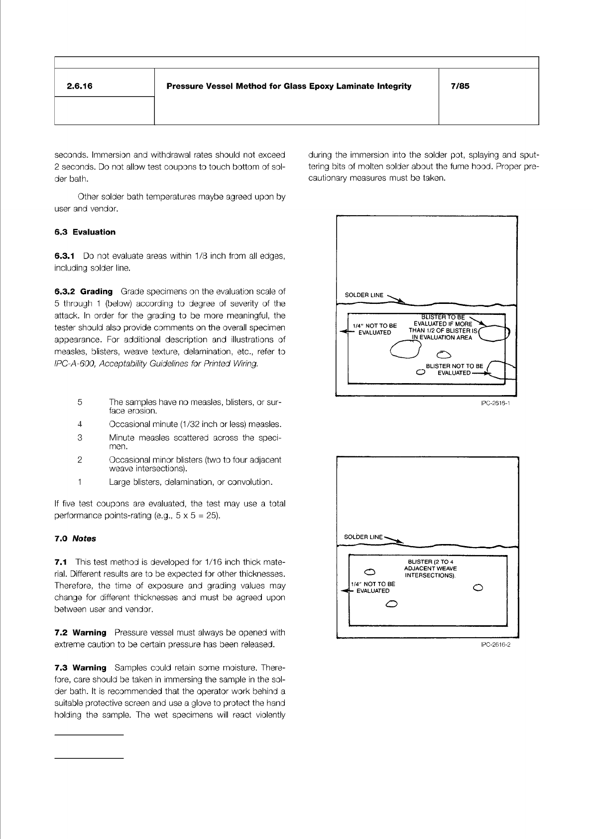
6.3.1
Do
not
evaluate
areas
within
1/8
inch
from
all
edges,
including
solder
line.
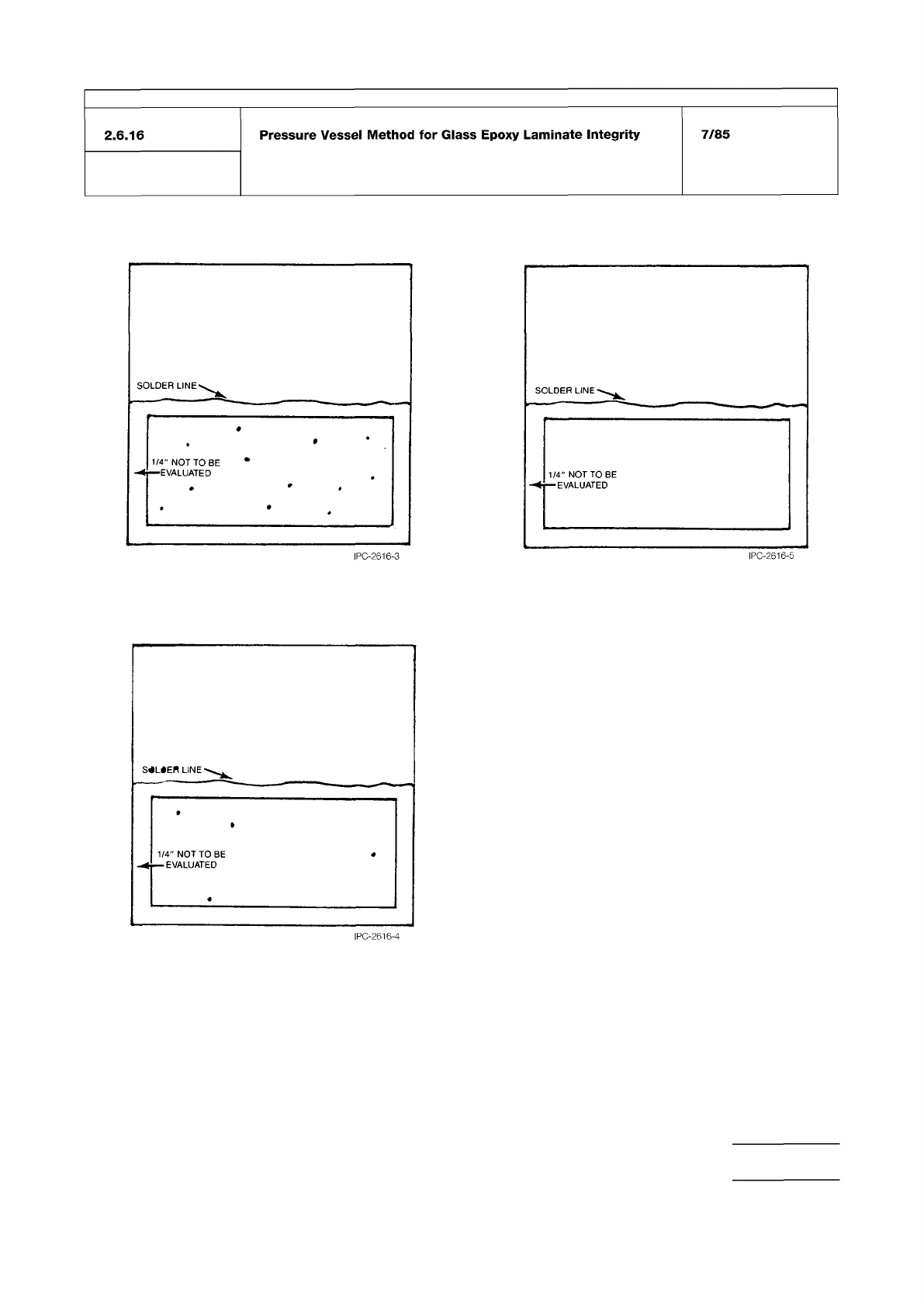
6.3.2
Grading
Grade
specimens
on
the
evaluation
scale
of
5
through
1
(below)
according
to
degree
of
severity
of
the
attack.
In
order
for
the
grading
to
be
more
meaningful,
the
tester
should
also
provide
comments
on
the
overall
specimen
appearance.
For
additional
description
and
illustrations
of
measles,
blisters,
weave
texture,
delamination,
etc.,
refer
to
IPC-A-600,
Acceptability
Guidelines
for
Printed
Wiring.
5
The
samples
have
no
measles,
blisters,
or
sur¬
face
erosion.
4
Occasional
minute
(1/32
inch
or
less)
measles.
3
Minute
measles
scattered
across
the
speci¬
men.
2
Occasional
minor
blisters
(two
to
four
adjacent
weave
intersections).
1
Large
blisters,
delamination,
or
convolution.
If
five
test
coupons
are
evaluated,
the
test
may
use
a
total
performance
points-rating
(e.g.,
5x5
=
25).
7.0
Notes
7.1
This
test
method
is
developed
for
1/16
inch
thick
mate¬
rial.
Different
results
are
to
be
expected
for
other
thicknesses.
Therefore,
the
time
of
exposure
and
grading
values
may
change
for
different
thicknesses
and
must
be
agreed
upon
between
user
and
vendor.
7.2
Warning
Pressure
vessel
must
always
be
opened
with
extreme
caution
to
be
certain
pressure
has
been
released.
7.3
Warning
Samples
could
retain
some
moisture.
There¬
fore,
care
should
be
taken
in
immersing
the
sample
in
the
sol¬
der
bath.
It
is
recommended
that
the
operator
work
behind
a
suitable
protective
screen
and
use
a
glove
to
protect
the
hand
holding
the
sample.
The
wet
specimens
will
react
violently
during
the
immersion
into
the
solder
pot,
splaying
and
sput¬
tering
bits
of
molten
solder
about
the
fume
hood.
Proper
pre¬
cautionary
measures
must
be
taken.
SOLDER
LINE
IPC-2616-1
SOLDER
LINE
BLISTER
(2
TO
4
—
-
ADJACENT
WEAVE
J
INTERSECTIONS).
1/4"
NOT
TO
BE
-
EVALUATED
o
o
IPC-2616-2
CONDITION 3
CONDITION 4
CONDITION 5
IPC-TM-650
Number
Subject Date
Revision
Page 3 of 3
2.6.16
Pressure
Vessel
Method
for
Glass
Epoxy
Laminate
Integrity
7/85
I
PC-261
6-4
IPC-A-600
IPC-TM-650 Test Methods Manual
Material in this Test Methods Manual was voluntarily established by Technical Committees of the IPC. This material is advisory only
and its use or adaptation is entirely voluntary. IPC disclaims all liability of any kind as to the use, application, or adaptation of this
material. Users are also wholly responsible for protecting themselves against all claims or liabilities for patent infringement.
Equipment referenced is for the convenience of the user and does not imply endorsement by the IPC.
Page 1 of 2
r
ASSOCIATION
CONNECTING
/
ELECTRONICS
INDUSTRIES
221
5
Sanders
Road
Northbrook,
IL
60062-6135
IPC-TM-650
TEST
METHODS
MANUAL
1
Scope
This
test
method
is
designed
to
determine
the
capability
of
HDI
materials
and
other
dielectrics
to
withstand
moisture
induced
stress
as
applied
by
extended
time
in
a
pressure
vessel.
For
laminated
constructions,
the
results
may
be
affected
by
the
process
conditions.
2
Applicable
Documents
Acceptability
of
Printed
Boards
2
.1.1
Microsectioning
2.1
.1
.2
Microsectioning
—
Semi
or
Automatic
Technique
Microsection
Equipment
(Alternate)
2.3.6
Etching,
Ammonium
Persulfate
Method
2.3.7
Etching,
Ferric
Chloride
Method
2.3.7.
1
Cupric
Chloride
Etching
Method
2.3.
7.
2
Alkaline
Etching
Method
3
Test
Specimen
3.1
Samples
shall
be
prepared
as
appropriate
for
the
type
of
material.
All
samples
shall
be
10
cm
x
10
cm
±
0.5
cm,
with
the
thickness
determined
by
the
type
of
material
(see
3.1.1
to
3.1
.3).
Three
samples
shall
be
prepared.
Control
samples
are
required
for
all
samples
where
the
dielectric
layer
is
applied
to
an
etched
laminate.
One
control
sample
of
the
etched
lami¬
nate
(with
no
added
dielectric)
is
required
for
samples
pre¬
pared
according
to
3.
1.2.
2
or
3.1.3.
3.1.1
Copper-Clad
Laminate
The
laminate
shall
have
all
copper
removed
in
accordance
with
IPC-TM-650,
Method
2.3.6,
2.3.7,
2.3.7.
1
or
2.
3.
7.2,
then
cut
to
dimensions
of
10
cm
x
1
0
cm
±
0.65
cm.
3.1.2
Semi-Cured
Prepreg
The
prepreg
shall
be
lami¬
nated
to
a
cured
sheet
configuration,
with
35
micron
copper
foil,
using
the
supplier's
recommended
lamination
cycle.
The
laminate
shall
be
etched
of
all
copper,
then
cut
to
dimensions
of
1
0
cm
x
1
0
cm
±
0.65
cm.
3.
1.2.1
Semi-Cured
Prepreg
or
Dielectric
Material,
Method
A
Sufficient
plies
of
prepreg
shall
be
used
to
result
in
a
composite
base
thickness
of
0.4
mm
±
0.1
mm.
If
the
prepreg
is
of
a
nature
that
does
not
allow
for
lamination
of
a
Number
2.6.16.1
Subject
Moisture
Resistance
of
High
Density
Interconnection
(HDI)
Materials
Under
High
Temperature
and
Pressure
(Pressure
Vessel)
Date
8/98
Revision
Originating
Task
Group
HDI
Test
Methods
Task
Group
(D-42A)
single
sample
of
the
thickness
specified,
then
a
thinner
sample
shall
be
laminated,
noting
the
thickness
as
part
of
the
report,
see
5.5.
3.
1.2.
2
Semi-Cured
Prepreg
or
Dielectric
Material,
Alternate
Method
B
The
prepreg
or
dielectric
layer
shall
be
laminated
to
both
sides
of
an
etched
laminate
that
has
a
thick¬
ness
of
0.4
mm
土
0.1
mm.
The
prepreg
or
dielectric
layer
shall
be
applied,
laminated
and
cured
according
to
the
manufactur¬
er's
recommendations.
Unless
otherwise
specified,
the
result¬
ing
prepreg
or
dielectric
layer
thickness
shall
be
a
nominal
of
0.05
mm
on
each
side
of
the core
laminate.
Optionally,
the
actual
thickness
may
be
measured
by
mechanical
or
cross-
sectional
methods
and
reported,
see
5.5.
Control
samples
shall
be
the
etched
laminate
core
with
no
prepreg
or
dielectric
layer.
3.1.3
Coated
Dielectrics
The
coated
dielectrics
(i.e.,
res¬
ins,
adhesives,
dry
films)
shall
be
applied
to
both
sides
of
an
etched
laminate
that
has
a
thickness
of
0.4
mm
±
0.1
mm.
The
coated
dielectrics
shall
be
applied
and
cured
according
to
the
manufacturer's
recommendations.
Unless
otherwise
specified,
the
resulting
coated
dielectric
thickness
shall
be
a
nominal
of
0.05
mm
on
each
side
of
the
core
laminate.
Optionally,
the
actual
thickness
may
be
measured
by
mechanical
or
cross-sectional
methods
and
reported,
see
55
Control
samples
shall
be
the
etched
laminate
core
with
no
coated
dielectric.
4
Test
Equipment
4.1
Pressure
vessel
capable
of
maintaining
a
constant
pres¬
sure
of
2
ATM
(14
psig),
and
a
temperature
of
121℃
±
2
℃,
with
water
content
maintained
for
a
minimum
of
six
hours
before
needing
replenishment.
4.2
Oven,
air
circulating,
capable
of
holding
a
temperature
of
105℃
±
2
℃
4.3
Microsectioning
equipment,
including
slug
cutter,
mounting,
grinding,
and
polishing
equipment
(see
IPC-TM-
650,
Method
2.1.1
or
2.
1.1.
2)
4.4
Microscope
capable
of
200X
magnification,
with
optional
photographic
equipment