IPC-TM-650 EN 2022 试验方法--.pdf - 第210页
1 Scope To determine the number of flexes to cond uctor failure of etched flexible printe d board conductor pa tterns. 2 Applicable Documents None 3 Test Specimen The test specimen consist of an etched conductor p attern…
Note:
IPC-TM-650
Note:
Note:
Note:
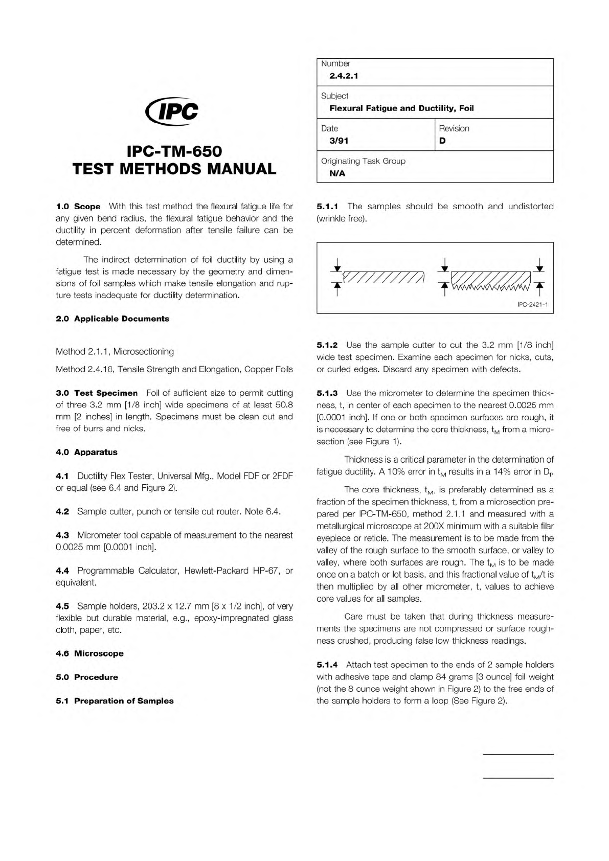
Figure 1 Smooth and rough foil
t
M
t
t = t
M
The Institute for Interconnecting and Packaging Electronic Circuits
2215 Sanders Road • Northbrook, IL 60062-6135
Material in this Test Methods Manual was voluntarily established by Technical Committees of the IPC. This material is advisory only
and its use or adaptation is entirely voluntary. IPC disclaims all liability of any kind as to the use, application, or adaptation of this
material. Users are also wholly responsible for protecting themselves against all claims or liabilities for patent infringement.
Equipment referenced is for the convenience of the user and does not imply endorsement by the IPC.
Page 1 of 3
IPC-TM-650
TEST
METHODS
MANUAL
1
.0
Scope
With
this
test
method
the
flexural
fatigue
life
for
any
given
bend
radius,
the
flexural
fatigue
behavior
and
the
ductility
in
percent
deformation
after
tensile
failure
can
be
determined.
The
indirect
determination
of
foil
ductility
by
using
a
fatigue
test
is
made
necessary
by
the
geometry
and
dimen¬
sions
of
foil
samples
which
make
tensile
elongation
and
rup¬
ture
tests
inadequate
for
ductility
determination.
2
.0
Applicable
Documents
Method
2.1.1,
Microsectioning
Method
2.4.18,
Tensile
Strength
and
Elongation,
Copper
Foils
3
.0
Test
Specimen
Foil
of
sufficient
size
to
permit
cutting
of
three
3.2
mm
[1/8
inch]
wide
specimens
of
at
least
50.8
mm
[2
inches]
in
length.
Specimens
must
be
clean
cut
and
free
of
burrs
and
nicks.
4
.0
Apparatus
4.1
Ductility
Flex
Tester,
Universal
Mfg.,
Model
FDF
or
2FDF
or
equal
(see
6.4
and
Figure
2).
4.2
Sample
cutter,
punch
or
tensile
cut
router.
Note
6.4.
4.3
Micrometer
tool
capable
of
measurement
to
the
nearest
0.0025
mm
[0.0001
inch].
4.4
Programmable
Calculator,
Hewlett-Packard
HP-67,
or
equivalent.
4.5
Sample
holders,
203.2
x
12.7
mm
[8
x
1/2
inch],
of
very
flexible
but
durable
material,
e.g.,
epoxy-impregnated
glass
cloth,
paper,
etc.
4.6
Microscope
5
.0
Procedure
Number
2.4.2.
1
Subject
Flexural
Fatigue
and
Ductility,
Foil
Date
Revision
3/91
D
Originating
Task
Group
N/A
5.1.1
The
samples
should
be
smooth
and
undistorted
(wrinkle
free).
5.1.2
Use
the
sample
cutter
to
cut
the
3.2
mm
[1/8
inch]
wide
test
specimen.
Examine
each
specimen
for
nicks,
cuts,
or
curled
edges.
Discard
any
specimen
with
defects.
5.1.3
Use
the
micrometer
to
determine
the
specimen
thick¬
ness,
t,
in
center
of
each
specimen
to
the
nearest
0.0025
mm
[0.0001
inch].
If
one
or
both
specimen
surfaces
are
rough,
it
is
necessary
to
determine
the
core
thickness,
tM
from
a
micro¬
section
(see
Figure
1).
Thickness
is
a
critical
parameter
in
the
determination
of
fatigue
ductility.
A
10%
error
in
tM
results
in
a
14%
error
in
Df.
The
core
thickness,
tM,
is
preferably
determined
as
a
fraction
of
the
specimen
thickness,
t,
from
a
microsection
pre¬
pared
per
IPC-TM-650,
method
2.1.1
and
measured
with
a
metallurgical
microscope
at
200X
minimum
with
a
suitable
filar
eyepiece
or
reticle.
The
measurement
is
to
be
made
from
the
valley
of
the
rough
surface
to
the
smooth
surface,
or
valley
to
valley,
where
both
surfaces
are
rough.
The
tM
is
to
be
made
once
on
a
batch
or
lot
basis,
and
this
fractional
value
of
tM/t
is
then
multiplied
by
all
other
micrometer,
t,
values
to
achieve
core
values
for
all
samples.
Care
must
be
taken
that
during
thickness
measure¬
ments
the
specimens
are
not
compressed
or
surface
rough¬
ness
crushed,
producing
false
low
thickness
readings.
5.1.4
Attach
test
specimen
to
the
ends
of
2
sample
holders
with
adhesive
tape
and
clamp
84
grams
[3
ounce]
foil
weight
(not
the
8
ounce
weight
shown
in
Figure
2)
to
the
free
ends
of
the
sample
holders
to
form
a
loop
(See
Figure
2).
5.1
Preparation
of
Samples
1 Scope
To determine the number of flexes to conductor
failure of etched flexible printed board conductor patterns.
2 Applicable Documents
None
3 Test Specimen
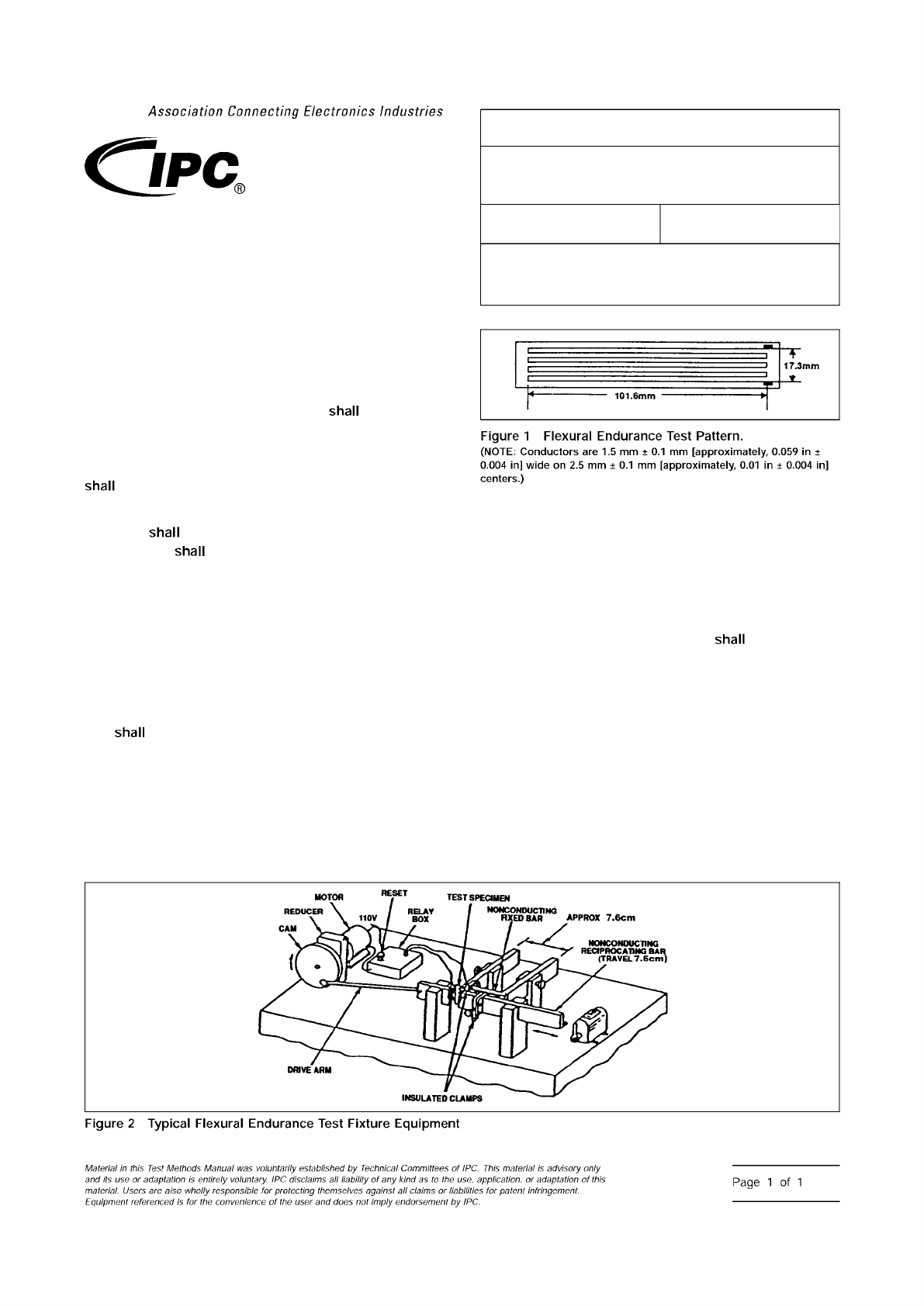
The test specimen consist of an
etched conductor pattern in accordance with Figure 1. A mini-
mum of six specimens with the long dimension of the conduc-
tors oriented in the transverse direction of the base material
be prepared using standard commercial practices.
For double-sided clad constructions, a separate sample
specimen
be prepared for each side. The opposite
(untested) side
be completely etched of copper.
4 Apparatus
Flexural Endurance Tester (see Figure 2) or
equivalent.
5 Procedures
5.1
Examine the etched conductor specimen for any pre-
existing fractures and look for evidence of process anomalies
(such as pin holes and nicks), which could cause premature
fracture. If such fractures or anomalies are found, the speci-
men
be discarded and a new specimen selected.
5.2
Attach (solder, clamp, etc.) a short length of insulated
wire to the extreme ends of the conductor pattern of each of
the six specimens.
5.3
Using the flexure test equipment as seen in Figure 2,
mount the specimen so that the inside diameter of the loop is
6 mm ± 1 mm [approximately, 0.25 in ± 0.04 in] and connect
the two wires to the relay. The horizontal oscillation of the
reciprocating bar causes the flexible test specimen to move in
what can be described as a rolling, flexible action.
5.4
Test three specimens per clad side with the conductor
on the inside of the loop. The reciprocating travel should not
exceed 10 cycles per minute. The loop
travel 25 mm ±
5 mm [effectively, 1 in ± 0.2 in].
5.5
The number of cycles to failure is when electrical discon-
tinuity of the conductor occurs.
5.6
Report the average number of cycles to failure for the
three specimens tested per clad side.
6 Note
Master set of drawings of a similar test fixture as
seen in Figure 2 is available from the IPC office. This fixture is
not commercially available.
IPC-243-1
IPC-243-2
3000 Lakeside Drive, Suite 309S
Bannockburn, IL 60015-1249
IPC-TM-650
TEST METHODS MANUAL
Number
2.4.3
Subject
Flexural Endurance, Flexible Printed Board
Materials
Date
6/11
Revision
E
Originating Task Group
Flexible Circuits Test Methods Subcommittee
(D-15)
Association
Connecting
Electronics
Industries
shall
shall
shall
Figure
1
Flexural
Endurance
Test
Pattern.
(NOTE:
Conductors
are
1.5
mm
±
0.1
mm
[approximately,
0.059
in
±
0.004
in]
wide
on
2.5
mm
±
0.1
mm
[approximately,
0.01
in
±
0.004
in]
centers.)
shall
Figure
2
Typical
Flexural
Endurance
Test
Fixture
Equipment
Material
M
this
历
sf
Methods
Manual
was
voluntarily
established
by
Technical
Committees
of
IPC.
This
material
is
advisory
only
and
its
use
or
adaptation
is
entirely
voluntary.
IPC
disclaims
liability
of
any
kind
as
to
the
use,
application,
or
adaptation
of
this
material.
Users
are
also
wholly
responsible
for
protecting
themselves
against
claims
or
liabililies
for
patent
infringement.
Equipment
referenced
/s
for
fhe
convenience
of
the
user
and
does
not
imply
endorsement
by
IPC.
Page
1
of
1
The Institute for Interconnecting and Packaging Electronic Circuits
2215 Sanders Road • Northbrook, IL 60062-6135
Material in this Test Methods Manual was voluntarily established by Technical Committees of the IPC. This material is advisory only
and its use or adaptation is entirely voluntary. IPC disclaims all liability of any kind as to the use, application, or adaptation of this
material. Users are also wholly responsible for protecting themselves against all claims or liabilities for patent infringement.
Equipment referenced is for the convenience of the user and does not imply endorsement by the IPC.
Page 1 of 3
IPC-TM-650
TEST
METHODS
MANUAL
1
Scope
The
purpose
of
the
two
test
methods
is
to
provide
means
for
determining
the
volatile
content
of
adhesive
coated
dielectric
films
used
in
the
manufacture
of
flexible
printed
wir¬
ing.
Method
A
is
a
weight
loss
procedure.
Method
B
is
a
headspace
gas
chromatography
procedure.
2
Applicable
Documents
None
3
Test
Specimen
3.1
Method
A
The
test
specimens
shall
be
squares
of
adhesive
coated
dielectric
film.
The
specimens
shall
be
1
0
cm
x
10
cm.
This
method
is
to
be
used
for
non-aqueous
solvent
systems
only.
3.2
Method
B
Three
specimens
shall
be
prepared:
One
specimen
shall
be
cut
from
the
center
of
the
material
and
one
each
from
each
edge
of
the
material.
Specimens
shall
be
cut
no
closer
than
25.4
mm
from
the
edge
of
the
material.
4
Equipment/Apparatus
4.1
Method
A
4.1.1
Analytical
Balance
Analytical
balance
capable
of
weighing
to
the
nearest
milligram
(0.001
gram).
4.1.2
Test
Chamber
Circulating
air
oven
maintained
at
150℃
±
2.8℃.
4.2
Method
B1
4.2.1
Analytical
Balance
Analytical
balance
capable
of
weighing
to
the
nearest
0.1
milligram
(0.0001
gram).
4.2.2
Sample
Vials
It
is
essential
that
the
septa
are
placed
with
the
Teflon®
side
toward
the
sample
and
that
the
vials
are
sealed
tightly
enough
that
it
is
not
possible
to
turn
the
lid
by
hand.
Number
2.3.37
Subject
Volatile
Content
of
Adhesive
Coated
Dielectric
Films
Date
Revision
5/98
B
Originating
Task
Group
Flex
Peel
Strength
Test
Methods
Task
Group
(D-13A)
4.2.3
Test
Device
A
gas
chromatograph
fitted
with
a
Head
Space
Sampler
and
a
data
acquisition/manipulation
system
capable
of
recording
and
quantitating
gas
chromatograms.
4.2.4
Chromatography
Conditions
Tenax
column
6.35
mm
O.D.
1
.8
m
long.
Injector
temperature:
Product
dependent
Oven
temperature:
Product
dependent
Isothermal
Flame
Ionization
Detector:
Carrier
gas
is
Nitrogen
at
kg/cm2
Adjust
equipment
conditions
for
specific
product
being
tested.
4.2.5
Headspace
Conditions
Temperature
and
dwell
time
dependent
on
product
tested.
5
Procedure
Method
A
5.1
Preparation
5.1.
1.1
Condition
each
specimen
at
50%
±
5%
relative
humidity
(RH)
and
23℃
士
2
℃
for
a
minimum
of
three
hours.
5.
1.1.2
Weigh
each
specimen
to
the
nearest
milligram
(0.001
gram)
[WJ
5.1.
1.3
Subtract
out
substrate
weight
by
calculating
the
area
x
the
density
of
the
substrate
under
test
(Ws).
5.1.
1.4
Hang
each
specimen
from
a
metal
hook
in
the
cir¬
culating
air
oven
at
150℃
±
2.8℃
for
15
±
1
minutes.
5.1.
1.5
Remove
each
specimen
from
the
chamber
and
place
in
a
stabilization
environment
of
50%
土
5%
RH
and
23℃
±
2
℃
for
a
minimum
of
three
hours.
5.1.
1.6
Reweigh
each
specimen
to
the
nearest
milligram
[WF].
5.1.
1.7
Subtract
out
substrate
weight
by
calculating
the
area
x
the
density
of
the
substrate
under
test
(Ws).
1
.
Method
B
requires
proprietary
information
regarding
the
constituents
of
the
material.