IPC-TM-650 EN 2022 试验方法--.pdf - 第723页
minimum IPC-TM-650 Page 2 of 3 Number 2.6.14.1 Revision Subject Electrochemical Migration Resistance Test Date 09/00 4.6 Other Dedicated Fixtures Hardwiring is the default connection method. Other dedicated fixtures may …
IPC-B-25
IPC-B-25A
IPC-6012A
IPC-9201
ASTM D-257-93
Figure 1 IPC-B-25A Test Board
Material in this Test Methods Manual was voluntarily established by Technical Committees of IPC. This material is advisory only
and its use or adaptation is entirely voluntary. IPC disclaims all liability of any kind as to the use, application, or adaptation of this
material. Users are also wholly responsible for protecting themselves against all claims or liabilities for patent infringement.
Equipment referenced is for the convenience of the user and does not imply endorsement by IPC.
Page 1 of 3
ASSOCIATION
CONNECTING
/
ELECTRONICS
INDUSTRIES
221
5
Sanders
Road
Northbrook,
IL
60062-61
35
IPC-TM-650
TEST
METHODS
MANUAL
1
Scope
This
test
method
provides
a
means
to
assess
the
propensity
for
surface
electrochemical
migration.
This
test
method
can
be
used
to
assess
soldering
materials
and/or
processes.
2
Applicable
Documents
2.1
IRC
Multipurpose
Test
Board
Multipurpose
Test
Board
Qualification
and
Performance
Specification
for
Rigid
Printed
Boards
Surface
Insulation
Resistance
Handbook
2.1
American
Society
for
Testing
and
Materials
(ASTM)
Standard
Test
Methods
for
DC
Resistance
or
Conductance
of
Insulating
Materials
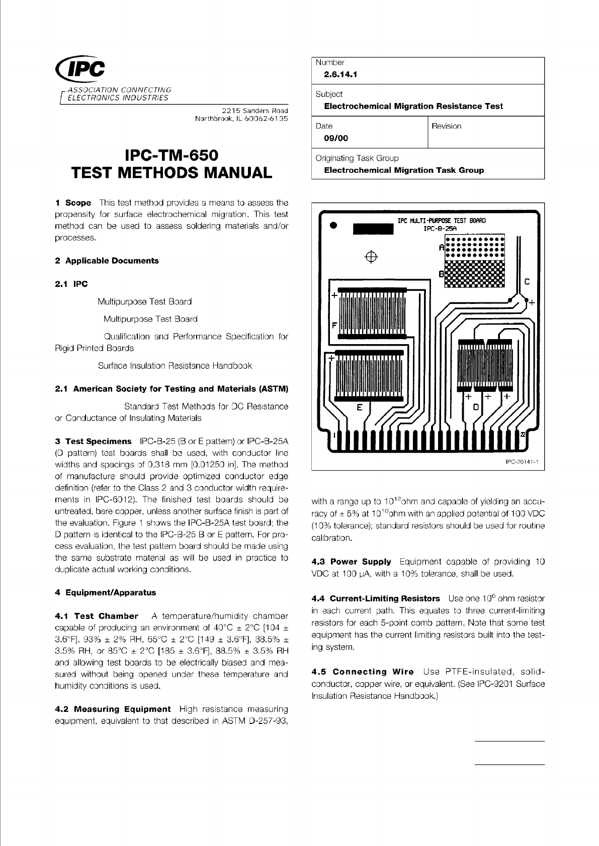
3
Test
Specimens
IPC-B-25
(B
or
E
pattern)
or
IPC-B-25A
(D
pattern)
test
boards
shall
be
used,
with
conductor
line
widths
and
spacings
of
0.318
mm
[0.01250
in].
The
method
of
manufacture
should
provide
optimized
conductor
edge
definition
(refer
to
the
Class
2
and
3
conductor
width
require¬
ments
in
IPC-601
2).
The
finished
test
boards
should
be
untreated,
bare
copper,
unless
another
surface
finish
is
part
of
the
evaluation.
Figure
1
shows
the
IPC-B-25A
test
board;
the
D
pattern
is
identical
to
the
IPG-B-25
B
or
E
pattern.
For
pro¬
cess
evaluation,
the
test
pattern
board
should
be
made
using
the
same
substrate
material
as
will
be
used
in
practice
to
duplicate
actual
working
conditions.
4
Equipment/Apparatus
4.1
Test
Chamber
A
temperature/humidity
chamber
capable
of
producing
an
environment
of
40℃
±
2
℃
[104
±
36F],
93%
土
2%
RH,
65℃
±
2
℃
[149
±
3.6°F],
88.5%
±
3.5%
RH,
or
85℃
+
2
℃
[185
土
3.6°F],
88.5%
土
3.5%
RH
and
allowing
test
boards
to
be
electrically
biased
and
mea¬
sured
without
being
opened
under
these
temperature
and
humidity
conditions
is
used.
Number
2.6.14.1
Subject
Electrochemical
Migration
Resistance
Test
Date
Revision
09/00
Originating
Task
Group
Electrochemical
Migration
Task
Group
IPG-261
41-1
with
a
range
up
to
1012ohm
and
capable
of
yielding
an
accu¬
racy
of
+
5%
at
101°ohm
with
an
applied
potential
of
100
VDC
(10%
tolerance);
standard
resistors
should
be
used
for
routine
calibration.
4.3
Power
Supply
Equipment
capable
of
providing
10
VDC
at
100
pA,
with
a
10%
tolerance,
shall
be
used.
4.4
Current-Limiting
Resistors
Use
one
1
03
6
ohm
resistor
in
each
current
path.
This
equates
to
three
current-limiting
resistors
for
each
5-point
comb
pattern.
Note
that
some
test
equipment
has
the
current
limiting
resistors
built
into
the
test¬
ing
system.
4.5
Connecting
Wire
Use
PTFE-insulated,
solid¬
conductor,
copper
wire,
or
equivalent.
(See
IPC-9201
Surface
Insulation
Resistance
Handbook.)
4.2
Measuring
Equipment
High
resistance
measuring
equipment,
equivalent
to
that
described
in
ASTM
D-257-93,
minimum
IPC-TM-650
Page 2 of 3
Number
2.6.14.1
Revision
Subject
Electrochemical
Migration
Resistance
Test
Date
09/00
4.6
Other
Dedicated
Fixtures
Hardwiring
is
the
default
connection
method.
Other
dedicated
fixtures
may
be
used,
provided
that
the
fixture
does
not
change
the
resistance
for
more
than
0.1
decade
compared
to
a
comparable
hardwired
system,
when
measured
at
the
test
conditions.
5
Procedure
5.1
Test
Specimen
Preparation
5.1.1
In
performing
a
material
qualification
(e.g.,
flux),
all
specimens
are
to
be
cleaned
and
dried
using
a
process
capable
of
yielding
a
insulation
resistance
value
of
4
x
1O10
ohm
when
tested
at
35℃,
85%
minimum
RH
after
24
hours.
If
this
test
is
being
performed
as
a
process
qualifi¬
cation,
additional
pre-test
processing
is
not
allowed.
5.1.2
A
minimum
of
three
test
specimens
cleaned
per
5.1
.1
shall
be
used
for
controls.
5.1.3
For
liquid
flux:
Apply
the
liquid
flux
to
the
entire
surface
of
the
test
specimen
by
brushing
liberal
quantities
of
the
flux
onto
the
specimen,
by
floating
the
specimen
comb
side
down
on
the
liquid
flux,
or
by
dipping
the
specimen
into
the
flux.
The
specimen
shall
be
drained
vertically
for
one
minute
with
the
fingers
of
the
comb
pattern
vertical.
Alternatively,
flux
may
be
applied
by
produc¬
tion
application
processes
-
spray,
foam,
or
wave.
The
edge
connector
fingers
should
be
protected
from
flux.
It
is
recommended
that
production
wave
soldering
equipment
be
used
for
soldering
the
test
specimens,
with
a
preheat
pro¬
file
representative
of
production.
A
solder
fountain
may
be
used
(not
a
solder
pot),
with
a
residence
time
similar
to
the
residence
time
in
a
solder
wave.
Solder
composition
is
usually
60%
tin
土
5%,
remainder
is
lead;
for
such
alloys,
the
solder
temperature
shall
be
250℃
土
6
℃
[482
±
10.8°F].
For
alloys
other
than
those
with
compositions
near
the
tin-lead
eutectic,
the
solder
temperature
will
be
compatible
with
the
usual
sol¬
dering
temperature
for
the
alloy
used.
If
any
solder
bridging
occurs,
that
specimen
shall
be
dis¬
carded.
A
minimum
of
three
specimens
from
the
sample
group
shall
be
tested.
5.1.4
For
solder
paste:
A
squeegee
or
screen
printer
shall
be
used
with
a
stencil
imaged
with
the
test
pattern.
It
should
be
noted
that
the
Tel¬
cordia
GR-78
pattern
requires
a
minimum
stencil
thickness
of
0.20
mm
[7.9
mil].
Due
to
the
fact
that
the
minimum
stencil
thickness
is
often
dependent
on
the
pitch
or
trace
width
and
spacing,
a
smaller
stencil
thickness
may
be
used
for
fine
fea¬
tures
and
shall
be
agreed
upon
between
the
tester
and
cus¬
tomer
for
the
purpose
of
this
test
method.
Reflow
the
printed
specimens
using
convection,
infrared,
or
vapor
phase
reflow
equipment
using
a
reflow
profile
represen¬
tative
of
production.
Equivalent
methods
may
be
used
if
such
equipment
is
not
available.
If
any
solder
bridging
occurs,
that
specimen
shall
be
dis¬
carded.
The
edge
connector
fingers
should
be
protected
from
paste.
A
minimum
of
three
specimens
from
the
sample
group
shall
be
tested.
5.1.5
For
flux-cored
wires:
Using
a
hand
soldering
iron
and
the
cored
wire
under
test,
carefully
apply
solder
to
the
fingers
of
all
comb
patterns.
The
edge
connector
fingers
should
be
protected
from
flux.
If
any
solder
bridging
occurs,
that
specimen
shall
be
dis¬
carded.
A
minimum
of
three
specimens
from
the
sample
group
shall
be
tested.
Each
circuit
path
will
be
tested
for
the
presence
of
solder
shorts
using
a
resistance
meter
(e.g.
digital
multimeter).
5.1.6
Post
solder
cleaning
shall
be
performed
only
when
such
cleaning
is
part
of
the
production
process
used
in
the
final
assembly.
5.1.7
When
evaluating
incoming
board
quality
and/or
final
finishes,
test
specimens
shall
be
used
as
received
or
as
speci¬
fied
by
the
end
user.
5.1
.8
Attach
test
leads
to
the
land
areas
of
all
patterns
either
by
mechanical
pressure
(e.g.,
edge
connectors,
spring-loaded
pins)
or
by
hand
soldering
using
Rosin
(R)
cored
wire,
using
a
shield
to
protect
the
test
patterns
from
flux
contamination
dur¬
ing
soldering;
the
flux
shall
not
spread
into
the
pattern
area.
Do
not
remove
the
flux.
5.2
Test
Procedure
5.2.1
Place
the
terminated
test
specimens
in
a
suitable
rack
that
maintains
the
specimens
at
least
2.5
cm
apart
and
such
that
the
air
flow
is
parallel
to
the
direction
of
the
test
speci¬
mens
in
the
chamber.
For
hardwiring,
wires
should
be
Note:
IPC-TM-650
Page 3 of 3
Number
2.6.14.1
Revision
Subject
Electrochemical
Migration
Resistance
Test
Date
09/00
dressed
from
the
bottom
to
prevent
flux
residues
from
the
wire
attachment
from
flowing
onto
the
test
patterns.
With
mechanical
fixtures,
fixtures
should
be
to
the
side.
Insert
the
limiting
resistors
in
terminating
leads
1
,
3,
and
5
of
each
pat¬
tern.
5.2.2
Place
the
rack
approximately
in
the
center
of
the
test
chamber.
Route
the
wires
to
the
outside
of
the
chamber;
dress
the
wiring
away
from
the
test
patterns.
Ensure
that
drops
of
condensation
cannot
fall
on
the
specimens.
5.2.3
Close
the
chamber
and
allow
all
samples
to
stabilize
for
96
hours
at
the
specific
temperature
and
humidity.
After
the
96-hour
stabilization
period,
the
initial
insulation
resistance
measurements
shall
be
made
using
voltage
in
the
range
of
45
VDC
to
100
VDC.
Due
to
polarity,
measurements
should
be
made
between
terminals
1
and
2,
3
and
2,
3
and
4,
and
5
and
4,
at
the
specific
temperature
and
humidity
with
the
current
limiting
resistors
placed
in
series
with
the
test
circuit.
Termi¬
nals
2
and
4
shall
be
at
one
potential,
and
terminals
1
,
3,
and
5
at
the
opposite
potential.
5.2.4
Connect
the
samples
to
the
power
supply
with
the
current
limiting
resistors
placed
in
series
with
the
test
circuit,
and
apply
1
0
VDC
for
the
duration
of
the
test.
The
test
polar¬
ity
shall
be
the
same
as
the
measurement
polarity
used
in
section
5.2.3.
5.2.5
After
500
hours
of
applied
bias
(596
hours
total),
dis¬
connect
the
power
supply
and
repeat
the
measurements
per
5.2.3
with
the
specimens
under
test
conditions.
5.3
Data
Handling
The
average
(geometric
mean)
insula¬
tion
resistance
(IRavg)
is
calculated
from:
1
N
IRavg
=
1
。
卜
斗
3
where,
N
二
number
of
test
points
(10
minimum),
IRi
=
individual
insulation
resistance
measurements
Where
an
assignable
cause
of
low
insulation
resistance,
which
is
properly
attributable
to
the
materials
of
construction
or
to
the
process
used
to
produce
the
test
board,
can
be
found,
then
such
a
value
can
be
excluded
from
calculating
the
aver¬
age.
Such
assignable
causes
include:
•
Contamination
on
the
insulating
surface
of
the
board,
such
as
debris,
solder
splints,
or
water
droplets
from
the
condi¬
tioning
chamber
•
Incompletely
etched
patterns
that
decrease
the
insulating
space
between
conductors
by
an
amount
greater
than
that
allowed
in
the
appropriate
design
requirements
drawing
•
Scratched,
cracked,
or
obviously
damaged
insulation
between
conductors
A
minimum
of
1
0
test
measurements
is
required
for
the
test
to
be
valid.
5.4
Visual
Examination
After
completion
of
the
test,
the
test
specimens
shall
be
removed
from
the
test
chamber
and
examined,
with
back-lighting,
at
10x
magnification
for
evi¬
dence
of
electrochemical
migration
(filament
growth),
discol¬
oration,
and
corrosion.
Localized
electrochemical
migration
on
one
comb
may
be
caused
by
a
testing
anomaly.
6
Notes
6.1
Reference
Documents
6.1.1
IPC-TR-476A
Electrochemical
Migration:
Electrically
Induced
Failures
in
Printed
Wiring
Assemblies
6.1.2
IPC-9201
Surface
Insulation
Resistance
Handbook
6.1.3
Telcordia
GR-78-CORE
6.2
Specification
of
Test
Conditions
Users
of
this
test
method
will
need
to
specify
one
(1)
of
the
three
(3)
temperature/humidity
conditions
called
out
in
section
4.1
.
Note
that
IPC-TR-476A
recommends
using
65℃,
85%
RH.