IPC-TM-650 EN 2022 试验方法--.pdf - 第659页
1 Scope This t est method is used to determine the mois- ture and insulation resistances of applied polymer so lder mask under two separate presc ribed conditions of t emperature and humidity. One condi tion i s describe…
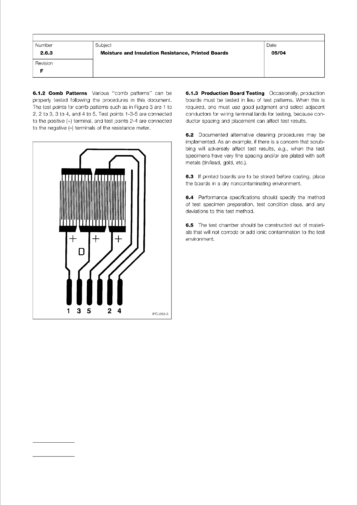
Figure 3 Typical ‘‘Comb Pattern’’ (from IPC-B-25A)
IPC-TM-650
Page 4 of 4
Number
2.6.3
Subject
Moisture
and
Insulation
Resistance,
Printed
Boards
Date
05/04
Revision
F
6.1.2
Comb
Patterns
Various
"comb
patterns"
can
be
properly
tested
following
the
procedures
in
this
document.
The
test
points
for
comb
patterns
such
as
in
Figure
3
are
1
to
2,
2
to
3,
3
to
4,
and
4
to
5.
Test
points
1-3-5
are
connected
to
the
positive
(+)
terminal,
and
test
points
2-4
are
connected
to
the
negative
(-)
terminals
of
the
resistance
meter.
6.1.3
Production
Board
Testing
Occasionally,
production
boards
must
be
tested
in
lieu
of
test
patterns.
When
this
is
required,
one
must
use
good
judgment
and
select
adjacent
conductors
for
wiring
terminal
lands
for
testing,
because
con¬
ductor
spacing
and
placement
can
affect
test
results.
6.2
Documented
alternative
cleaning
procedures
may
be
implemented.
As
an
example,
if
there
is
a
concern
that
scrub¬
bing
will
adversely
affect
test
results,
e.g.,
when
the
test
specimens
have
very
fine
spacing
and/or
are
plated
with
soft
metals
(tin/lead,
gold,
etc.).
6.3
If
printed
boards
are
to
be
stored
before
coating,
place
the
boards
in
a
dry
noncontaminating
environment.
6.4
Performance
specifications
should
specify
the
method
of
test
specimen
preparation,
test
condition
class,
and
any
deviations
to
this
test
method.
6.5
The
test
chamber
should
be
constructed
out
of
materi¬
als
that
will
not
corrode
or
add
ionic
contamination
to
the
test
environment.
1 Scope
This test method is used to determine the mois-
ture and insulation resistances of applied polymer solder mask
under two separate prescribed conditions of temperature and
humidity. One condition is described as Class T and the other
Class H. Raw material qualification testing is performed on
designated comb patterns. Production quality conformance
testing is performed on a standard ‘‘Y’’ pattern.
2 Applicable Documents
Multipurpose One-Sided Test Pattern -
Gerber Format
Qualification and Performance of Permanent
Solder Mask
Requirements for Soldering Fluxes
Acceptability for Printed Boards
3 Test Specimens
The IPC-A-25A-G-KIT artwork package
provides the Gerber files necessary for the fabrication of the
standard IPC-B-25A test board used with this test method.
3.1 Qualification Testing
3.1.1 Class H
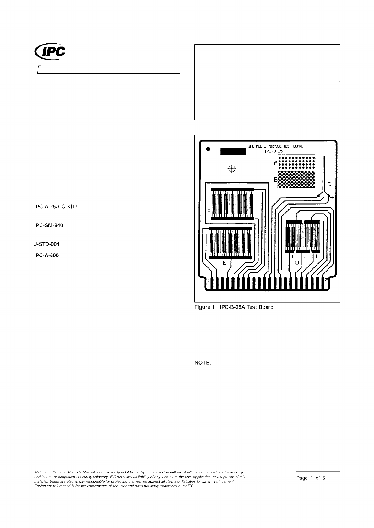
Three IPC-B-25A boards using the D comb
patterns with 0.32 mm [0.0126 in] lines/spaces (see Figure 1).
Of which, two are to be coated and one uncoated with solder
mask according to the solder mask supplier’s recommenda-
tions.
3.1.2 Class T
Three IPC-B-25A boards using the E and F
comb patterns with 0.41 mm [0.016 in] lines and 0.51 mm
[0.020 in] spaces (see Figure 1). Of which, two are to be
coated and one uncoated with solder mask according to the
solder mask supplier’s recommendations.
3.2 Conformance Testing
IPC-B-25A board C (‘‘Y’’
shape) pattern with 0.64 mm lines/0.64 mm spacing [0.025 in
lines/0.025 in spacing] or pattern with minimum spacing on
the production board (see Figure 1), whichever has the small-
est line spacing, coated with solder mask according to the
solder mask suppliers recommendations.
4 Apparatus
4.1 Chamber
A clean chamber capable of programming
and recording an environment of 25 ± 2 °C [77 ± 3.6 °F] to at
least 65 ± 2 °C [149 ± 3.6 °F] and 90-98% relative humidity.
This test requires a clean chamber and clean water
for repeatable test results. The following recommendations
are made:
• Incoming water purity should be between 0.5 and 0.1
micro-siemens/cm.
• Fresh deionized water should be used for each test, rather
than using a recirculating water sump.
• Chamber workspaces should be cleaned at least every six
months.
1. www.ipc.org/onlinestore
IPC-2631-1
3000 Lakeside Drive, Suite 309S
Bannockburn, IL 60015-1249
IPC-TM-650
TEST METHODS MANUAL
Number
2.6.3.1
Subject
Solder Mask - Moisture and Insulation Resistance
Date
03/07
Revision
E
Originating Task Group
Solder Mask Performance Task Group (5-33b)
ASSOCIATION CONNECTING
ELECTRONICS INDUSTRIES
®
IPC-A-25A-G-KIT1
IPC-SM-840
J-STD-004
IPC-A-600
Figure
1
IPC-B-25A
Test
Board
NOTE:
Material
in
this
Test
Methods
Manual
was
voluntarily
established
by
Technical
Committees
of
IPC.
material
advisory
only
and
its
use
or
adaptation
,
s
entirely
voluntary.
IPC
disclaims
all
liability
of
any
kind
as
to
the
use,
application,
or
adaptation
of
this
material.
Users
are
also
wholly
responsible
for
protecting
themselves
against
all
claims
or
liabilities
for
paten!
infringement.
Equipment
referenced
/s
the
convenience
of
the
user
and
does
not
imply
endorsement
by
IPC.
Page
1
of
5
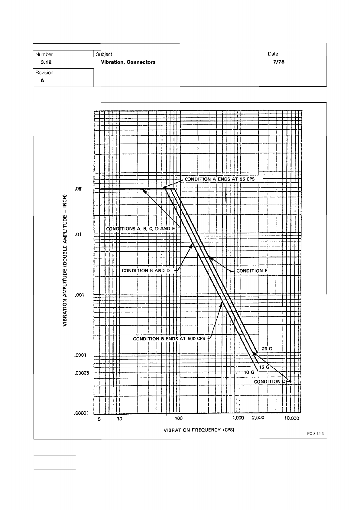
Figure 3 Vibration Test Curves
IPC-TM-650
Page 4 of 6
.0001
.00005
-
.00001
10
L000
2,000
10.000
VIBRATION
FREQUENCY
(CPS)
Number
3.12
Subject
Vibration,
Connectors
Date
7/75
Revision
A
1
00
^§5^
&mno
£
wwldwv
NOUVH
-
A
IPC-3-12-3