IPC-TM-650 EN 2022 试验方法--.pdf - 第735页
photolithographic processes such that a minimum of twelve good specimens are yielded at the end of 3.4.5. On the ‘ ‘Test Surface,’’ etch f our conductors 3 .2 m m [0.126 in] w ide, 5.7 mm [0.224 in] pitch, 230 - 250 mm […
1 Scope
This test method describes the procedure for
establishing the service temperature for metal-clad flexible
base material (laminate) as described in IPC-4204 as well as
cover materials and adhesive bonding films (unsupported
adhesive and supported bond plies) as described in IPC-
4203. For purposes of this test method, cover material
consist of coverlay and coverfilm but include cover-
coat materials. Properties evaluated after thermal aging in this
test are: visual, peel strength and dielectric strength.
2 Applicable Documents
2.1 IPC
1
Terms and Definitions for Interconnecting and
Packaging Electronic Circuits
Test Methods Manual
2
2.4.9 Peel Strength, Flexible Dielectric Materials
2.4.13 Solder Float Resistance Flexible Printed Wiring
Materials
Adhesive Coated Dielectric Films for Use as Cover
Sheets for Flexible Printed Circuitry and Flexible Adhesive
Bonding Films
Metal Foil for Printed Board Applications
2.2 ASTM International
3
Standard Test Method for Dielectric Break-
down Voltage and Dielectric Strength of Solid Electrical Insu-
lating Materials at Commercial Power Frequencies
3 Bond Strength Test Procedure
3.1 Specimen Preparation for Metal-Clad Flexible Base
Material (Laminate)
3.1.1
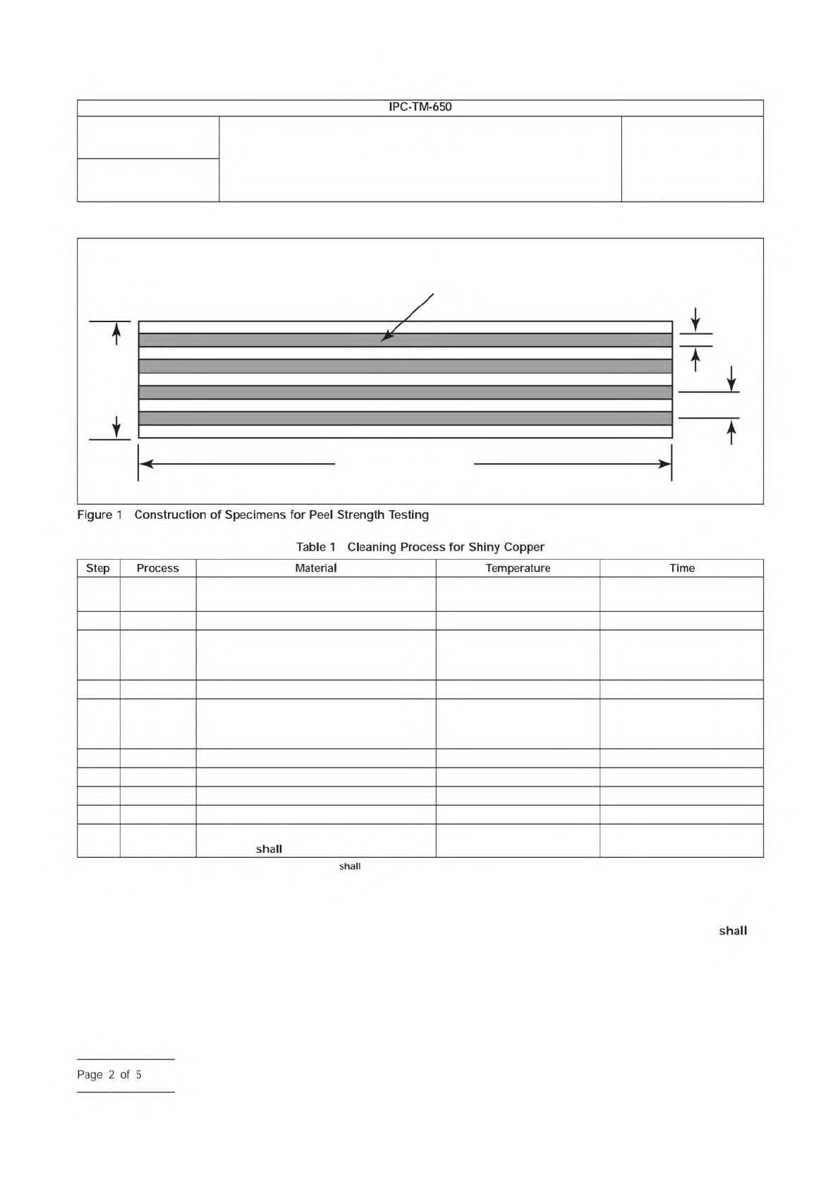
Prepare twelve specimens according to the procedure
outlined for method A of IPC TM-650, method 2.4.9, using
appropriate photolithographic processes. Etch four conduc-
tors 3.2 mm [0.126 in] wide, 5.7 mm [0.224 in] pitch, 230 -
250 mm [9 - 10 in] long on a nominal 25 mm [1 in] wide strip
of flexible base dielectric (see Figure 1).
Single-clad or double-clad flexible base material
be
tested in the format supplied. If the flexible base material
under test is double-clad, prepare a separate set of speci-
mens for each side. It is permissible to leave the unetched
copper on the non-test side (see Notes 6.1 and 6.2).
3.2 Specimen Preparation for Cover Material
3.2.1
Single-clad base material be produced from
specimens of the cover materials. Cover material
be
bonded to the shiny side of 34.3 µm [1.35 mil] copper foil,
type CU-E1-1S or CU-E7-1S per IPC-4562 (CU-E1-1S
be the referee material). Copper foil cleaning be per the
manufacturer’s normal cleaning procedure. The referee clean-
ing procedure
be per Table 1.
3.2.2
Prepare twelve specimens according to the procedure
outlined for method A of IPC TM-650, method 2.4.9, using
appropriate photolithographic processes. Etch four conduc-
tors 3.2 mm [0.126 in] wide, 5.7 mm [0.224 in] pitch, 230 -
250 mm [9 - 10 in] long on a nominal 25 mm [1 in] wide strip
of flexible base dielectric (see Figure 1).
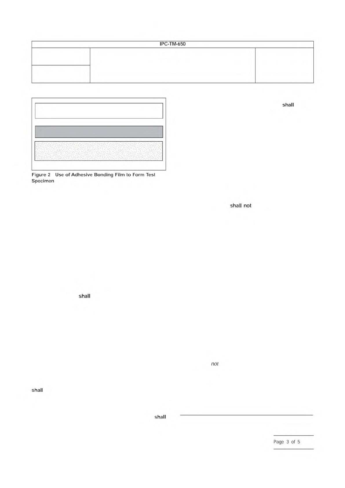
3.3 Specimen Preparation for Adhesive Bonding Film
3.3.1
Metal-clad flexible base material be produced
from specimens of the adhesive bonding film being evaluated.
Adhesive bonding film
be bonded to the shiny side of
34.3 µm [1350 µin] ED copper foil, type CU-E1-1S or RA
copper foil, CU-E7-1S per IPC-4562 (CU-E1-1S
be the
referee material). Adhesive bonding film
be bonded
between the copper foil and CU-E1-1S as support material as
illustrated in Figure 2. Copper foil cleaning
be per the
manufacturer’s normal cleaning procedure. The referee clean-
ing procedure
be per Table 1, the same as detailed in
IPC-4203.
Prepare specimens according to the procedure outlined for
method A of IPC TM-650, method 2.4.9, using appropriate
1. www.ipc.org
2. Current and revised IPC Test Methods are available on the IPC Web site (www.ipc.org/html/testmethods.htm)
3. www.astm.org
3000 Lakeside Drive, Suite 309S
Bannockburn, IL 60015-1249
IPC-TM-650
TEST METHODS MANUAL
Number
2.6.21
Subject
Service Temperature of Metal-Clad Flexible Laminate,
Cover Material and Adhesive Bonding Films
Date
6/11
Revision
B
Originating Task Group
Flexible Circuits Test Methods Subcommittee
(D-15)
Association
Connecting
Electronics
Industries
shall
shall
not
shall
IPC-T-50
IPC-TM-650
IPC-4203
IPC-4562
ASTM
D-149
shall
shall
shall
shall
shall
shall
shall
shall
shall
shall
shall
Material
/n
this
Test
Methods
Manual
was
voluntarily
established
by
Technical
Committees
of
I
PC.
This
material
/s
advisory
only
and
"s
use
or
adaptation
,
s
entirely
voluntary.
IPC
disclaims
all
liability
of
any
kind
as
to
the
use,
application,
or
adaptation
of
this
material.
Users
are
also
wholly
responsible
for
protecting
themselves
against
all
claims
or
liabilities
for
patent
infringement.
Equipment
referenced
/s
for
the
convenience
of
the
user
and
does
not
imply
endorsement
by
IPC.
Page
1
of
5
photolithographic processes such that a minimum of twelve
good specimens are yielded at the end of 3.4.5. On the ‘‘Test
Surface,’’ etch four conductors 3.2 mm [0.126 in] wide,
5.7 mm [0.224 in] pitch, 230 - 250 mm [9 - 10 in] long on a
nominal 25 mm [1 in] wide strip of flexible base dielectric (see
Figures 1 and 2).
3.4 Conditioning and Aging Procedure
3.4.1
Twelve specimens, as described in section 3, be
subjected to a stabilization period of a minimum of 24 hours
at 23 °C ± 2 °C [73.4 °F ± 3.6 °F] and 50% ± 5% RH.
IPC-2-6-21a
Metal Conductor (4 each)
3.2 mm
[0.126 in]
25 mm [1 in]
(nom.)
230–250 mm [9–10 in]
5.7 mm
[0.224 in]
1 Soak Clean
Use commercially available acid or alkaline
cleaners
Per supplier recommended
temperature
Per supplier recommended
time
2 Rinse Running tap water Room Temperature 3 - 5 minutes
3 Microetch
Sodium persulfate: Two liters of deionized
water, 280 grams of sodium persulfate,
25 cc sulfuric acid
Room Temperature 1 - 2 minutes
4 Rinse Running tap water Room Temperature 1 minute
5 Acid Dip
Sulfuric acid 10% by volume, dilution 1.8
liters deionized water, 200 cc sulfuric acid
96% assay
Room Temperature 45 seconds
6 Rinse Running tap water Room Temperature 1 minute
7 Rinse Deionized water Room Temperature 1 minute
8 Dry Force air dry or blot with paper towels Room Temperature 1 - 3 minutes
9 Bake Bake in clean air-circulating oven 110 ± 5 °C [230.0 ± 9.0 °F] 10 to 15 minutes
10 Lamination
*Maximum delay between bake and
lamination
be 30 minutes
*Lamination conditions (e.g., pressure, temperature, time, etc.) conform to suppliers’ recommendations.
Number
2.6.21
Subject
Service Temperature of Metal-Clad Flexible Laminate, Cover
Material and Adhesive Bonding Films
Date
6/11
Revision
B
IPC-TM-650
—
Figure
1
Construction
of
Specimens
for
Peel
Strength
Testing
Table
1
Cleaning
Process
for
Shiny
Copper
shall
Step
Process
Material
Temperature
Time
shall
shall
Page
2
of
5
3.4.2
Measure the flexible base dielectric thickness and the
metal thickness of the twelve specimens by micrometer, cali-
per or similar following the stabilization period in 3.4.1. Nomi-
nal metal thickness to be tested is either 1 oz or 34.3 µm
[1350 µin] thick (preferred) or
1
⁄
2
oz or 17.1 µm [680 µin] thick.
3.4.3
On the specimens stabilized in 3.4.1, measure and
verify that the conductor widths are 3.2 mm ± 0.15 mm
[0.126 in ± 5.9 µin].
3.4.4
Examine the twelve specimens measured in 3.4.3
using normal or corrected 20/20 (also termed 6/6 or 1.0)
vision, and discard any peel strips showing the presence of
any wrinkles, cracks, blisters, or loose conductors. Twelve
specimens are required for the test, so any specimens not
meeting this criterion
be replaced.
3.4.5
Per IPC-TM-650, TM 2.4.13, Method B, subject the
specimens examined in 3.4.4 to pre-drying and then solder
float.
3.4.6
Examine the specimens subjected to solder float in
3.4.5 using normal or corrected 20/20 (also termed 6/6 or 1.0)
vision. Discard any peel strips showing the presence of any
wrinkles, cracks, blisters, or loose conductors. Verify that at
least twelve good specimens remain.
3.4.7
Place six specimens into an air-circulating oven at the
desired Service Temperature value. The oven temperature
be held at a tolerance of ± 3°C [5.4 °F]. The specimens
are to continuously remain in the oven for 1000 hours, -0
hours / +12 hours.
3.4.8
After being aged per 3.4.7, the test specimens
be cooled to room temperature at standard ambient labora-
tory conditions. After being cooled to room temperature, the
thermally aged (oven conditioned) specimens
be sub-
jected to a stabilization period of a minimum of 24 hours at
23 °C ± 2 °C [73.4 °F ± 3.6 °F] and 50% ± 5% RH.
3.4.9
After the stabilization period in 3.4.8, examine the
specimens using normal or corrected 20/20 (also termed 6/6
or 1.0) vision, and record the presence of any wrinkles,
cracks, blisters, or loose conductors, or any delamination.
3.5 Measurement of Peel Strength
3.5.1
AABUS, test specimens may have rigid reinforcement
material attached to all twelve specimens that were subjected
to the solder float in 3.4.5, including those six specimens that
were additionally subjected to thermal aging in 3.4.7. The rigid
reinforcement material
be attached prior to condi-
tioning and aging. The attachment of the rigid reinforcement
material depends on a number of factors, including the type of
peel test apparatus as described in IPC-TM-650, Method
2.4.9. If the rigid reinforcement material is to be utilized, it
should be adhered to the specimens using double-faced
adhesive tape or appropriate adhesive system to the back
side of the specimens.
If the test specimens are generated from double-clad flexible
base materials with metal remaining on the non-test side, the
additional rigid reinforcement material is unnecessary and
should not be used.
3.5.2
Measure the peel strength of the twelve conductors
per the procedures outlined in IPC TM-650, Method 2.4.9.
Specifically, peel the etched copper conductors away from
the dielectric at a 90° angle and at a 50.8 mm [2 in] per min-
ute crosshead speed.
3.6 Document and Report Results
3.6.1
Calculate the average peel strength of the six speci-
mens that were only exposed to the solder float (i.e., only as
per 3.4.5 and
exposed to the thermal aging of 3.4.7). Do
the same for the six thermally aged specimens per 3.4.7. Cal-
culate the ratio of the ‘‘thermally aged’’ average peel
strengths divided by the solder-floated only average peel
strength to determine the percentage retention of peel
strength. Record this number to ± 1% accuracy.
[Ave. of Six (6) Peel Strengths of Thermally Aged Specimens]
[Ave. of Six (6) Peel Strengths of Solder Floated-Only Specimens
x 100 = % of Peel Strength Retained
IPC-2-6-21-2
1 oz ED or RA Copper Foil Test Surface
(Shiny side toward the adhesive)
1 oz ED Copper Foil with Treated Matte
Side Inward as Support Material
Adhesive Bonding Film
Number
2.6.21
Subject
Service Temperature of Metal-Clad Flexible Laminate, Cover
Material and Adhesive Bonding Films
Date
6/11
Revision
B
IPC-TM-650
Figure
2
Use
of
Adhesive
Bonding
Film
to
Form
Test
Specimen
shall
not
shall
shall
shall
Page
3
of
5