IPC-TM-650 EN 2022 试验方法--.pdf - 第789页
Figure 1 IPC-TM-650 Page 2 of 2 1.35V 3 POSITION (CENTER OFF) KNIFESWITCH MICROVOLTMETER TEST SAMPLE MEASURING RESISTOR (+1% ACCURACY) IPC-3-7-1 6.0 Notes 6.1 Acceptance criteria shall be established as the maxi¬ mum lev…
NOTE:
NOTE:
CAUTION:
NOTE:
Material in this Test Methods Manual was voluntarily established by Technical Committees of the IPC. This material is advisory only
and its use or adaptation is entirely voluntary. IPC disclaims all liability of any kind as to the use, application, or adaptation of this
material. Users are also wholly responsible for protecting themselves against all claims or liabilities for patent infringement.
Equipment referenced is for the convenience of the user and does not imply endorsement by the IPC.
Page 1 of 2
r
ASSOCIATION
CONNECTING
/
ELECTRONICS
INDUSTRIES
2215
Sanders
Road
Northbrook,
IL
60062-6135
IPC-TM-650
TEST
METHODS
MANUAL
1
.0
Scope
1.1
To
evaluate
the
contact
resistance
of
electrical
contacts
where
the
applied
voltage
and
current
are
low.
2
.0
Reference
Documents
2.1
Information
in
this
section
is
intended
to
parallel
the
test
method
described
in
EIA-RS-364/TP-23.
3
.0
Test
Specimen
3.1
The
mated
contacts
of
a
connector
mounted
and,
when
required,
terminated
in
its
normal
manner
or
a
mated
pair
of
individual
contacts.
When
mated
contact
pairs,
not
requiring
housings,
are
tested,
they
shall
be
rigidly
mounted
in
a
fixture
to
provide
mechanical
stability
and
to
insure
proper
mating
and
orienta¬
tion.
3.2
Voltage
connections
shall
be
attached
permanently
by
soldering,
crimping,
or
wire-wrapping
as
appropriate
and
shall
be
positioned
as
follows:
A.
Wire
Hole
—
On
the
contact
within
1/8
inch
of
insulator.
B.
WrapPost
—
On
the
wrap-post
adjacent
to
the
outer
turn
of
wire.
C.
Crimp
—
Crimped
to
the
contact
simultaneously
with
the
current
lead.
D.
Solder
Tab
—
On
the
printed
wiring
traces
as
close
to
the
termination
as
practicable.
E.
Press-Fit
——
On
the
pad
of
the
plated-th
rough
hole
as
close
to
the
termination
as
practicable.
If
the
pad
of
the
printed
wiring
board
constitutes
one-half
of
the
mated
contact
pair,
the
voltage
connection
shall
be
sol¬
dered
to
the
pad
immediately
adjacent
to,
but
not
touching,
the
mating
contact.
In
case
of
environment
resistant
(sealed)
connector,
the
voltage
connections
shall
be
attached
as
close
to
the
seal¬
ing
grommets
as
practicable.
Number
3.7
Subject
Low
Level
Circuit
Connectors
Date
Revision
7/75
A
Originating
Task
Group
N/A
3.3
Unless
otherwise
specified
in
the
individual
contact
or
connector
specification,
the
test
samples
shall
not
be
cleaned
by
any
means
prior
to
the
test
nor
shall
any
lubricants
or
other
coatings
be
applied.
4
.0
Apparatus
4.1
Microvoltmeter
The
meter
accuracy
shall
be
such
that
the
voltage
value
is
measured
within
2
percent.
4.2
Milliammeter
(optional)
The
meter
accuracy
shall
be
such
that
the
current
value
is
measured
within
2
percent.
4.3
0.001
OHM
resistor
accurate
to
±
1
percent.
4.4
Power
supply
capable
of
delivering
1
milliampere
at
1
.35
volts
DC
potential.
5
.0
Procedure
THE
CONTACTS
UNDER
TEST
SHALL
NOT
BE
SUBJECTED
TO
A
POTENTIAL
GREATER
THAN
20
MILLI¬
VOLTS
DC
(OR
20
MILLIVOLTS
PEAK
AC)
EITHER
PRIOR
TO
OR
DURING
THE
TEST.
5.1
The
low
level
test
shall
be
conducted
using
a
circuit
comparable
to
that
shown
in
Figure
1
,
which
will
deliver
a
one
milliampere
sample
current
when
the
variable
resistor
is
adjusted
to
provide
a
20
millivolt
open
circuit
potential
between
Tl
and
T2.
The
3-position
switch
shown
in
Figure
1
shall
be
opened
before
each
measurement
to
zero
the
voltme¬
ter.
The
total
resistance
between
points
T1
and
T2
shall
be
less
than
1
00
milliohms.
5.2
The
voltage
drop
across
each
pair
of
mated
contacts
with
the
current
successively
in
both
directions
through
the
test
specimen
shall
be
measured.
The
contact
resistance
shall
be
calculated,
in
both
the
forward
and
reverse
direction,
by
dividing
the
voltage
drop
reading
by
the
current
reading.
The
average
of
the
two
resistance
values
thus
obtained
for
each
contact
shall
not
exceed
the
maximum
allowable
contact
resistance
as
defined
in
the
individual
contact
or
connector
specification.
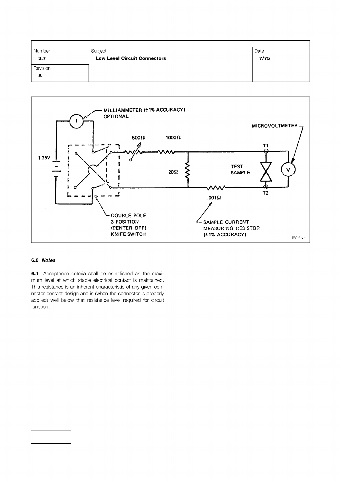
Figure 1
IPC-TM-650
Page 2 of 2
1.35V
3
POSITION
(CENTER
OFF)
KNIFESWITCH
MICROVOLTMETER
TEST
SAMPLE
MEASURING
RESISTOR
(+1%
ACCURACY)
IPC-3-7-1
6.0
Notes
6.1
Acceptance
criteria
shall
be
established
as
the
maxi¬
mum
level
at
which
stable
electrical
contact
is
maintained.
This
resistance
is
an
inherent
characteristic
of
any
given
con¬
nector
contact
design
and
is
(when
the
connector
is
properly
applied)
well
below
that
resistance
level
required
for
circuit
function.
Number
3.7
Subject
Low
Level
Circuit
Connectors
Date
7/75
Revision
A
Material in this Test Methods Manual was voluntarily established by Technical Committees of the IPC. This material is advisory only
and its use or adaptation is entirely voluntary. IPC disclaims all liability of any kind as to the use, application, or adaptation of this
material. Users are also wholly responsible for protecting themselves against all claims or liabilities for patent infringement.
Equipment referenced is for the convenience of the user and does not imply endorsement by the IPC.
Page 1 of 5
r
ASSOCIATION
CONNECTING
/
ELECTRONICS
INDUSTRIES
2215
Sanders
Road
Northbrook,
IL
60062-6135
IPC-TM-650
TEST
METHODS
MANUAL
1
.0
Scope
1
.1
To
determine
the
effect
on
the
connector
of
the
stresses
produced
by
transient
acceleration
or
deceleration
forces
resulting
from
handing,
transportation,
or
field
operation.
2
.0
Reference
Documents
2.1
Information
in
this
section
is
intended
to
parallel
the
test
method
described
in
EIA-RS-364/TP-27.
3
.0
Test
Specimen
3.1
A
connector
(plug
and
receptacle)
complete
with
appli¬
cable
guide,
keying,
and
engaging
hardware
or
a
card-
edge
receptacle
and
mating
nominal-thickness
printed
circuit
board.
3.2
Mounting
and
Termination
3.2.1
Right
Angle,
Two-Piece
Connector
The
receptacle
shall
be
mounted
and
terminated
normally
during
this
test;
receptacles
designed
for
mounting
on
non-rigid
bases
(e.g.,
motherboards,
metal-plate
back
panels,
etc.)
shall
be
mounted
on
the
smallest
section
of
such
a
base
that
will
accommodate
the
test
specimen.
The
plug
shall
be
termi¬
nated
normally
during
the
test
and
shall
be
mounted
on
a
nominal-thickness
printed
circuit
board
extending
the
full
width
of
the
plug;
the
board
shall
extend
a
minimum
of
four
inches
from
the
receptacle
when
the
connector
is
mated.
3.2.2
Card-Edge
Receptacle
The
receptacle
shall
be
mounted
and
terminated
normally
during
this
test
(see
3.2.1).
The
mating
printed
circuit
board
shall
extend
the
full
width
of
the
receptacle
and
shall
extend
a
minimum
of
four
inches
from
the
receptacle
when
mated.
3.2.3
Parallel,
Two-Piece
Connector
The
receptacle
and
plug
shall
be
terminated
normally
during
this
test;
both
com¬
ponents
shall
be
mounted
on
nominal-thickness
printed
circuit
boards
extending
the
full
width
of
each.
The
printed
circuit
boards
shall
extend
a
minimum
of
four
inches
from
each
com¬
ponent
when
the
connector
is
mated.
Number
3.8
Subject
Mechanical
Shock,
Connectors
Date
Revision
7/75
A
Originating
Task
Group
N/A
3.3
Fixturing
3.3.1
Right
Angle
Connector
The
test
specimen
shall
be
held
in
an
adequate
resonant
free
fixture.
(Figure
1
,
Reference
Example.)
3.3.2
Parallel
Connector
The
test
specimen
shall
be
held
in
an
adequate
resonant
free
fixture.
(Figure
2,
Reference
Example.)
3.4
The
connector
shall
be
wire
(or
printed
circuit
boards)
designed
such
that
a
continuous
electrical
circuit
(comprising
all
contacts
in
series)
is
formed
when
the
plug
(or
board)
and
receptacle
are
mated.
4.0
Apparatus
4.1
A
shock
machine
capable
of
producing
the
specified
input
shock
pulse
as
shown
in
Figures
3
and
4.
The
machine
may
be
of
a
free-
or
accelerated-fall,
resilient
rebound,
non-
resilient,
hydraulic
or
pneumatic
actuated,
or
other
type.
4.2
A
shock
measurement
system
consisting
of
an
accelera¬
tion
sensitive
transducer
(accelerometer)
and
appropriate
impedance
matching,
amplifying
and
recording
instrumenta¬
tion.
The
entire
system
shall
exhibit
a
frequency
response
within
the
limits
shown
in
Figure
5.
4.2.1
A
piezoelectric
accelerometer
used
as
the
transducer
shall
have
a
minimum
fundamental
resonant
frequency
of
14
KHz
(a
resonant
frequency
>30
KHz
is
recommended).
For
suitable
low
frequency
response,
the
RC
time
constant
of
the
accelerometer
and
its
load
shall
be
RC
>0.2
where:
R
-
load
resistance
(ohms)
C
-
accelerometer
capacitance,
plus
shunt
capacitance
of
the
load
and
the
inter-connecting
cable
(farads)
4.2.2
A
strain
gage
accelerometer
used
as
the
transducer
shall
have
a
minimum
undamped
natural
frequency
>1500
Hz,
with
damping
from
0.64
to
0.70
of
critical.