IPC-TM-650 EN 2022 试验方法--.pdf - 第737页
3.6.2 Report the results o f the visual examination eva luation in 3.4.9. 4 Dielectric Strength Using A STM D-149 Test Procedure 4.1 Speci men Preparation 4.1.1 Prepare a specimen of the metal-clad flexible base mater ia…
3.4.2
Measure the flexible base dielectric thickness and the
metal thickness of the twelve specimens by micrometer, cali-
per or similar following the stabilization period in 3.4.1. Nomi-
nal metal thickness to be tested is either 1 oz or 34.3 µm
[1350 µin] thick (preferred) or
1
⁄
2
oz or 17.1 µm [680 µin] thick.
3.4.3
On the specimens stabilized in 3.4.1, measure and
verify that the conductor widths are 3.2 mm ± 0.15 mm
[0.126 in ± 5.9 µin].
3.4.4
Examine the twelve specimens measured in 3.4.3
using normal or corrected 20/20 (also termed 6/6 or 1.0)
vision, and discard any peel strips showing the presence of
any wrinkles, cracks, blisters, or loose conductors. Twelve
specimens are required for the test, so any specimens not
meeting this criterion
be replaced.
3.4.5
Per IPC-TM-650, TM 2.4.13, Method B, subject the
specimens examined in 3.4.4 to pre-drying and then solder
float.
3.4.6
Examine the specimens subjected to solder float in
3.4.5 using normal or corrected 20/20 (also termed 6/6 or 1.0)
vision. Discard any peel strips showing the presence of any
wrinkles, cracks, blisters, or loose conductors. Verify that at
least twelve good specimens remain.
3.4.7
Place six specimens into an air-circulating oven at the
desired Service Temperature value. The oven temperature
be held at a tolerance of ± 3°C [5.4 °F]. The specimens
are to continuously remain in the oven for 1000 hours, -0
hours / +12 hours.
3.4.8
After being aged per 3.4.7, the test specimens
be cooled to room temperature at standard ambient labora-
tory conditions. After being cooled to room temperature, the
thermally aged (oven conditioned) specimens
be sub-
jected to a stabilization period of a minimum of 24 hours at
23 °C ± 2 °C [73.4 °F ± 3.6 °F] and 50% ± 5% RH.
3.4.9
After the stabilization period in 3.4.8, examine the
specimens using normal or corrected 20/20 (also termed 6/6
or 1.0) vision, and record the presence of any wrinkles,
cracks, blisters, or loose conductors, or any delamination.
3.5 Measurement of Peel Strength
3.5.1
AABUS, test specimens may have rigid reinforcement
material attached to all twelve specimens that were subjected
to the solder float in 3.4.5, including those six specimens that
were additionally subjected to thermal aging in 3.4.7. The rigid
reinforcement material
be attached prior to condi-
tioning and aging. The attachment of the rigid reinforcement
material depends on a number of factors, including the type of
peel test apparatus as described in IPC-TM-650, Method
2.4.9. If the rigid reinforcement material is to be utilized, it
should be adhered to the specimens using double-faced
adhesive tape or appropriate adhesive system to the back
side of the specimens.
If the test specimens are generated from double-clad flexible
base materials with metal remaining on the non-test side, the
additional rigid reinforcement material is unnecessary and
should not be used.
3.5.2
Measure the peel strength of the twelve conductors
per the procedures outlined in IPC TM-650, Method 2.4.9.
Specifically, peel the etched copper conductors away from
the dielectric at a 90° angle and at a 50.8 mm [2 in] per min-
ute crosshead speed.
3.6 Document and Report Results
3.6.1
Calculate the average peel strength of the six speci-
mens that were only exposed to the solder float (i.e., only as
per 3.4.5 and
exposed to the thermal aging of 3.4.7). Do
the same for the six thermally aged specimens per 3.4.7. Cal-
culate the ratio of the ‘‘thermally aged’’ average peel
strengths divided by the solder-floated only average peel
strength to determine the percentage retention of peel
strength. Record this number to ± 1% accuracy.
[Ave. of Six (6) Peel Strengths of Thermally Aged Specimens]
[Ave. of Six (6) Peel Strengths of Solder Floated-Only Specimens
x 100 = % of Peel Strength Retained
IPC-2-6-21-2
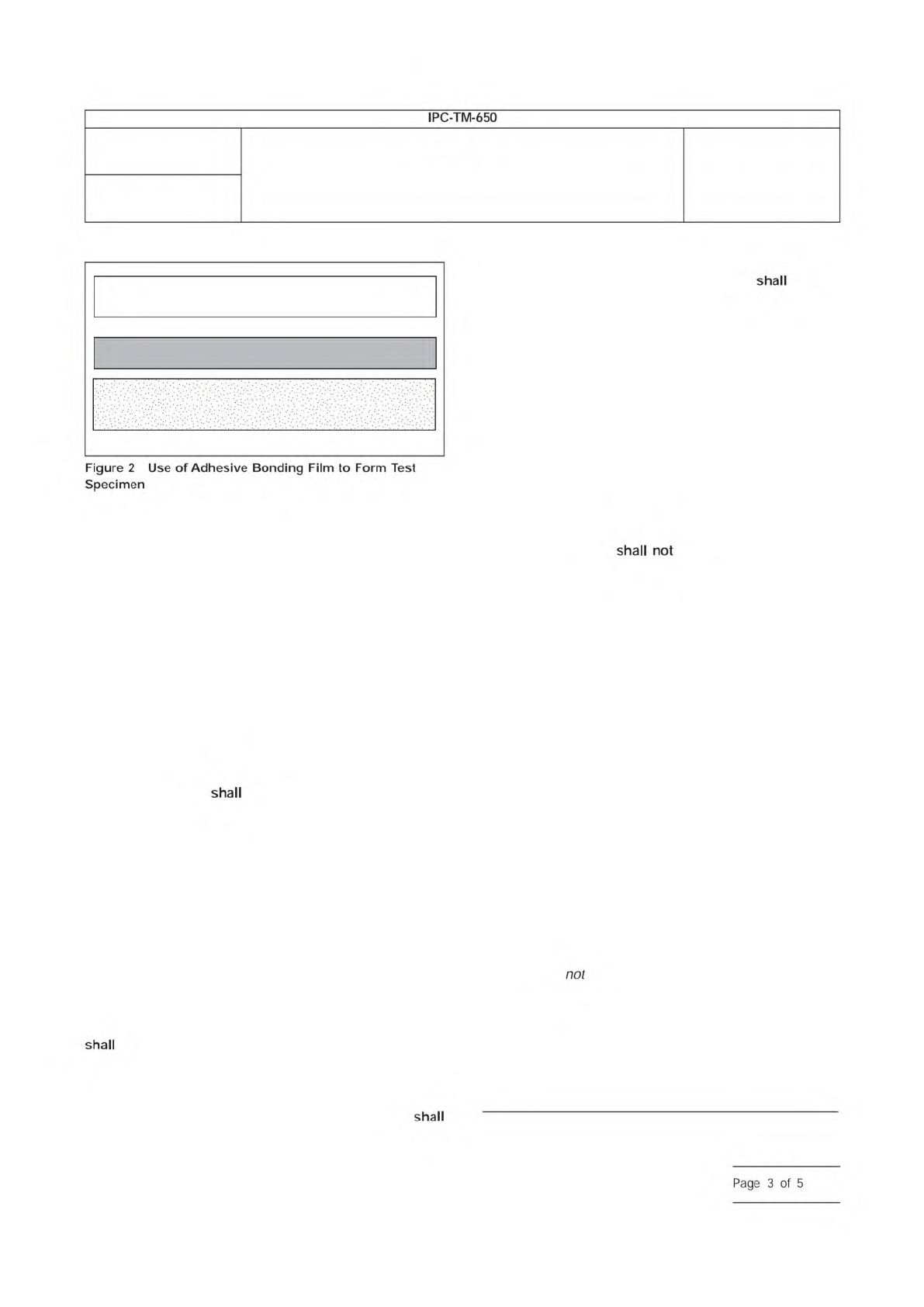
1 oz ED or RA Copper Foil Test Surface
(Shiny side toward the adhesive)
1 oz ED Copper Foil with Treated Matte
Side Inward as Support Material
Adhesive Bonding Film
Number
2.6.21
Subject
Service Temperature of Metal-Clad Flexible Laminate, Cover
Material and Adhesive Bonding Films
Date
6/11
Revision
B
IPC-TM-650
Figure
2
Use
of
Adhesive
Bonding
Film
to
Form
Test
Specimen
shall
not
shall
shall
shall
Page
3
of
5
3.6.2
Report the results of the visual examination evaluation
in 3.4.9.
4
Dielectric Strength Using ASTM D-149 Test Procedure
4.1 Specimen Preparation
4.1.1
Prepare a specimen of the metal-clad flexible base
material large enough [approximately 400 mm x 500 mm
[approx. 16 in x 20 in]] to prepare at least twelve test speci-
mens each of 80 mm x 80 mm [approx. 3.0 in x 3.0 in]. Cover
materials
be prepared per 3.2. Adhesive bonding films
be prepared per 3.3 where copper foil is used on both
sides of the adhesive bonding film.
4.1.2
Remove (etch) all metal from both surfaces of the
400 mm x 500 mm [approx. 16 in x 20 in] specimen by stan-
dard industry practice. Rinse the etched material thoroughly.
Cut the minimum of twelve test specimens to their nominal
size of 80 mm x 80 mm [approx. 3.0 in x 3.0 in].
4.2 Conditioning and Aging Procedure
4.2.1
After generating the minimum of twelve specimens as
described in 4.1.1, all specimens
be subjected to a sta-
bilization period of a minimum of 24 hours at 23 °C ± 2 °C
[73.4 °F ± 3.6 °F] and 50% RH ± 5% RH.
4.2.2
Examine at least twelve specimens using normal or
corrected 20/20 (also termed 6/6 or 1.0) vision, and record
any presence of any wrinkles, cracks or blisters. Discard those
specimens showing the presence of any wrinkles, cracks or
blisters.
4.2.3
Six specimens examined in 4.2.2 be placed into
an air-circulating oven at the desired Service Temperature
value. The oven temperature
be held at a tolerance of ±
3 °C [± 5.4 °F]. The specimens are to continuously remain in
the oven for 1000 hours, -0 hours / +12 hours.
4.2.4
After being oven-conditioned as described in 4.2.3,
the test specimens
be cooled to room temperature at
standard ambient laboratory conditions. After being cooled to
room temperature, the oven-conditioned specimens
be
subjected to a stabilization period of a minimum of 24 hours
at 23 °C ± 2° C [73.4 °F ± 3.6 °F] and 50% ± 5% RH.
4.2.5
After the stabilization period in 4.2.4, examine the six
specimens that had been subjected to the oven- conditioning
using normal or corrected 20/20 (also termed 6/6 or 1.0)
vision, and record the presence of any wrinkles, cracks or
blisters.
4.3 Measurement of Dielectric Strength
4.3.1
The six specimens that were not subjected to the
oven-conditioning in 4.2.3
be subjected to the dielectric
strength test per ASTM D-149. (These measurements
be considered the ‘‘as-received’’ dielectric strength values.)
4.3.2
The ‘‘thermally aged’’ (oven-conditioned) specimens
examined in 4.2.5
be tested for dielectric strength
according to the conditions outlined in 4.3.1. (These measure-
ments
be considered the ‘‘thermally-aged’’ dielectric
strength values.)
4.4 Evaluation of Results
4.4.1
Calculate the average dielectric strength of the six
‘‘as-received’’ specimens as measured in 4.3.1. Calculate the
average dielectric strength of the six ‘‘thermally aged’’ speci-
mens as measured in 4.3.2. Calculate the ratio of the average
value of the ‘‘thermally aged’’ dielectric strength divided by
the average value of the ‘‘as-received’’ dielectric strength to
determine the percentage retention of dielectric strength.
Record this number to ± 1% accuracy.
[Ave. of Six (6) Diel. Strengths of ‘‘Thermally Aged’’ Specimens]
[Ave. of Six (6) Diel. Strengths of ‘‘As Received’’ Specimens
x 100 = % of Dielectric Strength Retained
Number
2.6.21
Subject
Service Temperature of Metal-Clad Flexible Laminate, Cover
Material and Adhesive Bonding Films
Date
6/11
Revision
B
IPC-TM-650
shall
shall
shall
shall
shall
shall
shall
shall
shall
Page
4
of
5
5 Data Reporting
5.1
Report both percent values calculated in sections 3.6.1
and 4.4.1. The Service Temperature value, in units of °C,
be based upon the lesser of the two reported percent
values calculated in sections 3.6.1 and 4.4.1.
6 Notes
6.1
For specimen preparation, test results may vary
between specimens where the copper remains and those that
have had the copper removed from the nontest side. If the
flexible base material is supplied as single-clad and double-
clad, both must be tested.
6.2
For specimen preparation, test results may vary for the
same flexible base material, depending whether it is tested as
single- or double-clad.
6.3
Suitable procedures must be used to ensure that solder
does not remain on the test specimens after solder float.
6.4
For flexible base materials other than polyimide, the tem-
perature of the solder pot may be other than 288 °C [550 °F],
AABUS.
Number
2.6.21
Subject
Service Temperature of Metal-Clad Flexible Laminate, Cover
Material and Adhesive Bonding Films
Date
6/11
Revision
B
IPC-TM-650
shall
Page
5
of
5