IPC-TM-650 EN 2022 试验方法--.pdf - 第792页
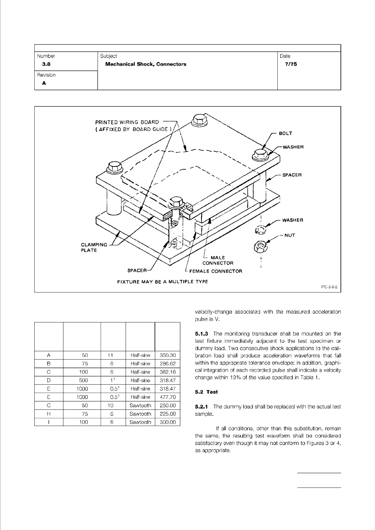
NOTE: Figure 2 Parallel Connector Fixture (S uggested) T able I T est Conditions T e st Condition Peak Acceleration A-Gravity Units Nominal Duration D-Milli- seconds W aveform V elocity Change Vi (G-MS) IPC-TM-650 Page 3…
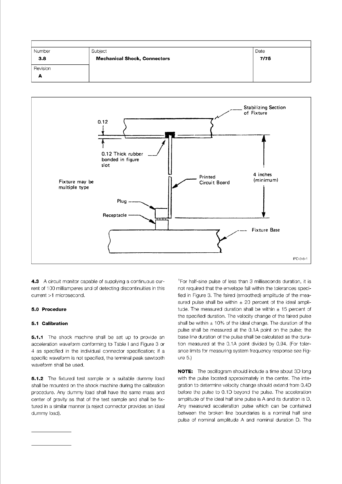
Figure 1 Right Angle Connector Fixture (Suggested)
IPC-TM-650
Page 2 of 5
Number
3.8
Subject
Mechanical
Shock,
Connectors
Date
7/75
Revision
A
IPC-3-8-1
4.3
A
circuit
monitor
capable
of
supplying
a
continuous
cur¬
rent
of
100
milliamperes
and
of
detecting
discontinuities
in
this
current
>1
microsecond.
5.0
Procedure
5.1
Calibration
5.1.1
The
shock
machine
shall
be
set
up
to
provide
an
acceleration
waveform
conforming
to
Table
I
and
Figure
3
or
4
as
specified
in
the
individual
connector
specification;
if
a
specific
waveform
is
not
specified,
the
terminal
peak
sawtooth
waveform
shall
be
used.
5.1.2
The
fixtured
test
sample
or
a
suitable
dummy
load
shall
be
mounted
on
the
shock
machine
during
the
calibration
procedure.
Any
dummy
load
shall
have
the
same
mass
and
center
of
gravity
as
that
of
the
test
sample
and
shall
be
fix¬
tured
in
a
similar
manner
(a
reject
connector
provides
an
ideal
dummy
load).
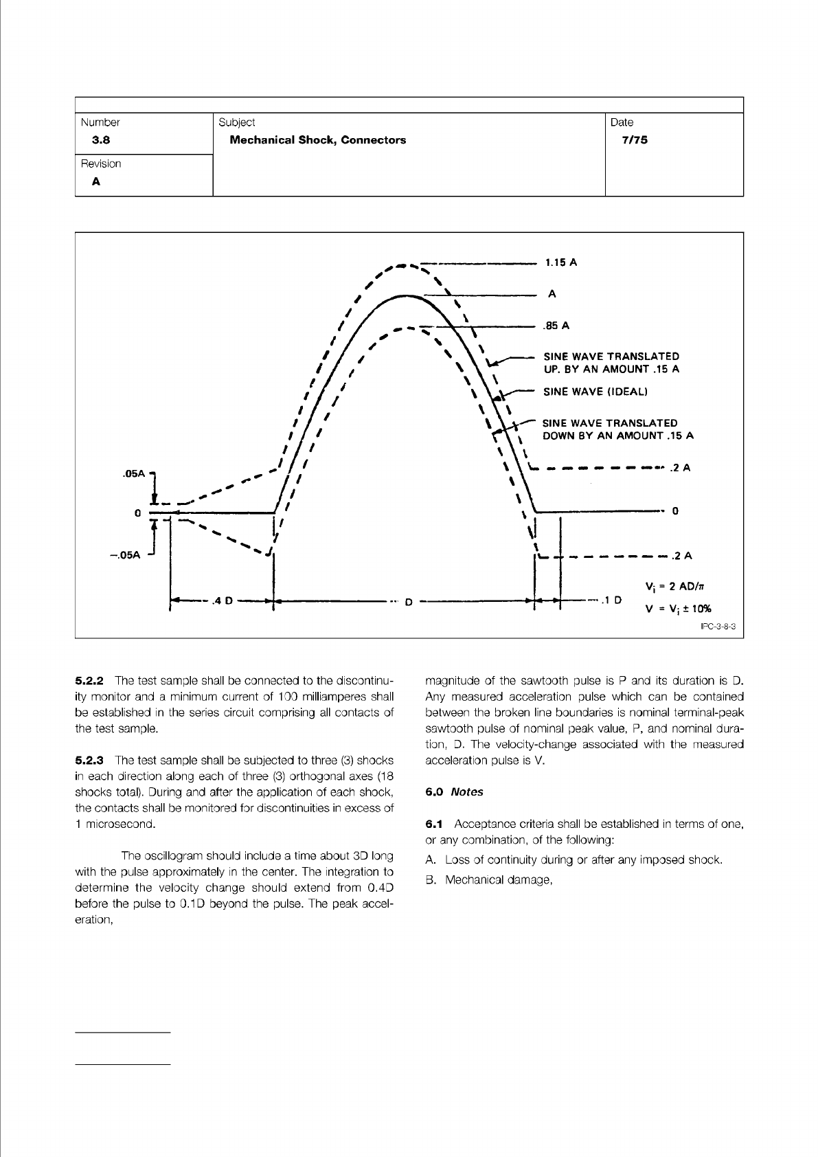
〔
For
half-sine
pulse
of
less
than
3
milliseconds
duration,
it
is
not
required
that
the
envelope
fall
within
the
tolerances
speci¬
fied
in
Figure
3.
The
faired
(smoothed)
amplitude
of
the
mea¬
sured
pulse
shall
be
within
土
20
percent
of
the
ideal
ampli¬
tude.
The
measured
duration
shall
be
within
±
15
percent
of
the
specified
duration.
The
velocity
change
of
the
faired
pulse
shall
be
within
±
10%
of
the
ideal
change.
The
duration
of
the
pulse
shall
be
measured
at
the
0.1A
point
on
the
pulse;
the
base
line
duration
of
the
pulse
shall
be
calculated
as
the
dura¬
tion
measured
at
the
0.1A
point
divided
by
0.94.
(For
toler¬
ance
limits
for
measuring
system
frequency
response
see
Fig¬
ure
5.)
NOTE:
The
oscillogram
should
include
a
time
about
3D
long
with
the
pulse
located
approximately
in
the
center.
The
inte¬
gration
to
determine
velocity
change
should
extend
from
0.4D
before
the
pulse
to
0.1
D
beyond
the
pulse.
The
acceleration
amplitude
of
the
ideal
half
sine
pulse
is
A
and
its
duration
is
D.
Any
measured
acceleration
pulse
which
can
be
contained
between
the
broken
line
boundaries
is
a
nominal
half
sine
pulse
of
nominal
amplitude
A
and
nominal
duration
D.
The
NOTE:
Figure 2 Parallel Connector Fixture (Suggested)
Table I
Test Conditions
Test
Condition
Peak
Acceleration
A-Gravity
Units
Nominal
Duration
D-Milli-
seconds Waveform
Velocity
Change
Vi
(G-MS)
IPC-TM-650
Page 3 of 5
Number
3.8
Subject
Mechanical
Shock,
Connectors
Date
7/75
Revision
A
FIXTURE
MAY
BE
A
MULTIPLE
TYPE
IPC-3-8-2
A
50
11
Half-sine
350.30
B
75
6
Half-sine
286.62
C
100
6
Half-sine
382.16
D
500
11
Half-sine
318.47
E
1000
0.51
Half-sine
318.47
F
5000
0.51
Half-sine
477.70
G
50
10
Sawtooth
250.00
H
75
6
Sawtooth
225.00
I
100
6
Sawtooth
300.00
velocity-change
associated
with
the
measured
acceleration
pulse
is
V.
5.1.3
The
monitoring
transducer
shall
be
mounted
on
the
test
fixture
immediately
adjacent
to
the
test
specimen
or
dummy
load.
Two
consecutive
shock
applications
to
the
cali¬
bration
load
shall
produce
acceleration
waveforms
that
fall
within
the
appropriate
tolerance
envelope;
in
addition,
graphi¬
cal
integration
of
each
recorded
pulse
shall
indicate
a
velocity
change
within
10%
of
the
value
specified
in
Table
1
.
5.2
Test
5.2.1
The
dummy
load
shall
be
replaced
with
the
actual
test
sample.
If
all
conditions,
other
than
this
substitution,
remain
the
same,
the
resulting
test
waveform
shall
be
considered
satisfactory
even
though
it
may
not
conform
to
Figures
3
or
4,
as
appropriate.
NOTE:
Figure 3 Tolerances for Half Sine Shock Pulse
IPC-TM-650
Page 4 of 5
Number
3.8
Subject
Mechanical
Shock,
Connectors
Date
7/75
Revision
A
5.2.2
The
test
sample
shall
be
connected
to
the
discontinu¬
ity
monitor
and
a
minimum
current
of
100
milliamperes
shall
be
established
in
the
series
circuit
comprising
all
contacts
of
the
test
sample.
5.2.3
The
test
sample
shall
be
subjected
to
three
(3)
shocks
in
each
direction
along
each
of
three
(3)
orthogonal
axes
(18
shocks
total).
During
and
after
the
application
of
each
shock,
the
contacts
shall
be
monitored
for
discontinuities
in
excess
of
1
microsecond.
The
oscillogram
should
include
a
time
about
3D
long
with
the
pulse
approximately
in
the
center.
The
integration
to
determine
the
velocity
change
should
extend
from
0.4D
before
the
pulse
to
0.1D
beyond
the
pulse.
The
peak
accel¬
eration,
magnitude
of
the
sawtooth
pulse
is
P
and
its
duration
is
D.
Any
measured
acceleration
pulse
which
can
be
contained
between
the
broken
line
boundaries
is
nominal
terminal-peak
sawtooth
pulse
of
nominal
peak
value,
P,
and
nominal
dura¬
tion,
D.
The
velocity-change
associated
with
the
measured
acceleration
pulse
is
V.
6.0
Notes
6.1
Acceptance
criteria
shall
be
established
in
terms
of
one,
or
any
combination,
of
the
following:
A.
Loss
of
continuity
during
or
after
any
imposed
shock.
B.
Mechanical
damage,