IPC-TM-650 EN 2022 试验方法--.pdf - 第587页
ASTM-B-193 The Institute for Int erconnecting and Packaging E lectronic Circuits 2215 Sanders Road • Northbrook, IL 60062 Material in this T est M ethods Manual was voluntarily establis hed by T echni cal Committees of t…
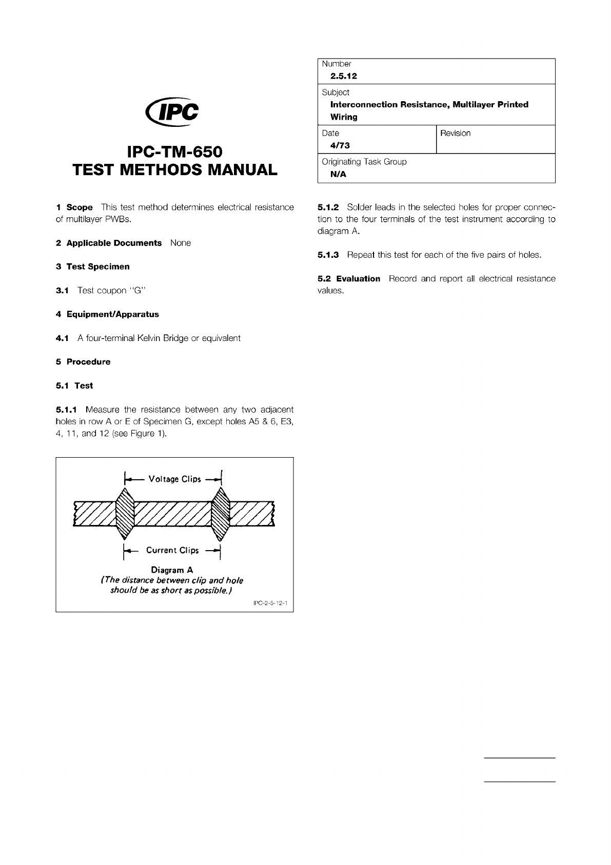
Figure 1 Distance from Clips
The Institute for Interconnecting and Packaging Electronic Circuits
2215 Sanders Road • Northbrook, IL 60062
Material in this Test Methods Manual was voluntarily established by Technical Committees of the IPC. This material is advisory only
and its use or adaptation is entirely voluntary. IPC disclaims all liability of any kind as to the use, application, or adaptation of this
material. Users are also wholly responsible for protecting themselves against all claims or liabilities for patent infringement.
Equipment referenced is for the convenience of the user and does not imply endorsement by the IPC.
Page 1 of 1
回
IPC-TM-650
TEST
METHODS
MANUAL
1
Scope
This
test
method
determines
electrical
resistance
of
multilayer
PWBs.
2
Applicable
Documents
None
3
Test
Specimen
3.1
Test
coupon
"G”
4
Equipment/Apparatus
4.1
A
four-terminal
Kelvin
Bridge
or
equivalent
5
Procedure
5.1
Test
5.1.1
Measure
the
resistance
between
any
two
adjacent
holes
in
row
A
or
E
of
Specimen
G,
except
holes
A5
&
6,
E3,
4,
11
,
and
12
(see
Figure
1).
Diagram
A
(The
distance
between
dip
and
hole
should
be
as
short
as
possible.)
Number
2.5.12
Subject
Interconnection
Resistance,
Multilayer
Printed
Wiring
Date
Revision
4/73
Originating
Task
Group
N/A
5.1.2
Solder
leads
in
the
selected
holes
for
proper
connec¬
tion
to
the
four
terminals
of
the
test
instrument
according
to
diagram
A.
5.1.3
Repeat
this
test
for
each
of
the
five
pairs
of
holes.
5.2
Evaluation
Record
and
report
all
electrical
resistance
values.
I
PC-2-5-1
2-1
ASTM-B-193
The Institute for Interconnecting and Packaging Electronic Circuits
2215 Sanders Road • Northbrook, IL 60062
Material in this Test Methods Manual was voluntarily established by Technical Committees of the IPC. This material is advisory only
and its use or adaptation is entirely voluntary. IPC disclaims all liability of any kind as to the use, application, or adaptation of this
material. Users are also wholly responsible for protecting themselves against all claims or liabilities for patent infringement.
Equipment referenced is for the convenience of the user and does not imply endorsement by the IPC.
Page 1 of 1
IPC-TM-650
TEST
METHODS
MANUAL
1
Scope
This
test
method
is
used
to
determine
the
resistiv¬
ity
of
copper
foil.
2
Applicable
Documents
Resistivity
of
Conductive
Materials
3
Test
Specimen
3.1
Three
samples
should
be
selected
at
equal
distances
across
the
width
of
the
material
from
each
lot
and
the
width
and
gauge
length
measured
to
the
nearest
0.025
mm.
4
Equipment/Apparatus
4.1
Tester
The
resistance
of
the
samples
shall
be
mea¬
sured
with
instruments
of
suitable
sensitivity
(see
ASTM-B-
193).
5
Procedure
5.1
Test
5.1.1
Resistance
Determination
Three
samples
shall
be
selected
at
equal
distances
across
the
width
of
the
material
from
each
lot
and
the
width
and
gauge
length
measured
to
the
nearest
0.025
mm.
The
resistance
of
the
samples
shall
be
measured
with
instruments
of
suitable
sensitivity,
in
accor¬
dance
with
ASTM-B-193.
5.1.2
For
convenience,
the
distance
between
test
points
may
be
15
cm,
and
the
weight
of
the
2.5
cm
wide
sample
being
measured
is
determined
by
weighing
a
2.5
cm
x
1
5
cm
strip
from
the
test
specimen.
Number
2.5.13
Subject
Resistance
of
Copper
Foil
Date
Revision
3/76
A
Originating
Task
Group
N/A
5.2
Evaluation
5.2.1
Calculate
the
resistance
using
the
formula:
Rt
%
=
1
+
aT
(t
-
T)
where:
T
=
reference
temperature
(20℃)
t
二
temperature
at
which
measurement
is
made
(
℃)
aT
二
temperature
coefficient
of
resistance
(0.00388)
Rt
=
resistance
at
reference
temperature
(20℃)
Rt
=
measured
resistance
5.2.2
Calculate
weight
resistivity
in
ohms
-
gram/meter2
using
the
formula:
Pw
=
^Rt
l1l2
where:
W
二
weight
of
test
specimen
(grams)
L
=
gauge
length
(meters)
L2
二
length
of
test
specimen
(meters)
Rt
=
resistance
at
reference
temperature
(20℃)
Note:
If
the
procedure
described
in
5.1
.2
is
used,
then:
L1
L2
Therefore
is
(0.1524
meters)2
or:
p
weight
of
0.040
mm
x
0.235
mm
specimen
门
where:
where:
NOTE:
Material in this Test Methods Manual was voluntarily established by Technical Committees of the IPC. This material is advisory only
and its use or adaptation is entirely voluntary. IPC disclaims all liability of any kind as to the use, application, or adaptation of this
material. Users are also wholly responsible for protecting themselves against all claims or liabilities for patent infringement.
Equipment referenced is for the convenience of the user and does not imply endorsement by the IPC.
Page 1 of 3
r
ASSOCIATION
CONNECTING
/
ELECTRONICS
INDUSTRIES
221
5
Sanders
Road
Northbrook,
IL
60062-6135
IPC-TM-650
TEST
METHODS
MANUAL
1
.0
Scope
1
.1
Purpose
This
test
method
covers
procedures
for
deter¬
mining
the
electrical
resistivity
of
copper
foil.
It
provides
for
an
accuracy
of
土
0.30
percent
of
test
specimens
having
a
resis¬
tance
of
0.00001
ohm
(10
microhms)
or
more.
1.2
Definition
Resistivity
is
the
electrical
resistance
of
a
body
of
unit
length
and
unit
cross-sectional
area
or
unit
weight.
Volume
resistivity
is
commonly
expressed
in
ohms
for
a
theoretical
conductor
of
unit
length
and
cross-sectional
area;
in
English
units
in
ohm-circular
mil/ft
and
in
metric
units
in
ohm-mm1
2
5/meter.
It
may
be
calculated
by
the
following
for¬
mula:
p.
=
volume
resistivity
in
ohm-circular
mil/ft
or
ohm-mm2
/meter,
A
二
cross-sectional
area
in
circular
mils,
or
sq
mm,
L
=
gauge
length,
used
to
determine
R,
in
ft,
or
m,
and
R
=
measured
resistance
in
ohms.
Weight
resistivity
is
commonly
expressed
in
ohms
for
a
theo¬
retical
conductor
of
unit
length
and
weight.
The
method
for
calculating
weight
resistivity,
based
on
resistance,
length,
and
weight
measurements,
of
a
test
specimen
is
given
in
Note
2.
2
.0
Applicable
Documents
None
3
.0
Test
Specimen
The
test
specimen
must
have
the
fol¬
lowing
characteristics:
1
.
A
resistance
of
at
least
0.00001
ohm
(1
0
microhms)
in
the
test
length
between
potential
contacts,
2.
A
test
length
of
at
least
1
ft
or
30
cm,
3.
A
thickness,
width
or
other
dimension
suitable
to
the
limi¬
tations
of
the
resistance
measuring
instrument,
4.
No
surface
cracks
or
defects
visible
to
the
unaided
nor¬
mal
eye,
and
substantially
free
from
surface
oxide,
dirt
and
grease,
5.
No
joints
or
splices.
Number
2.5.14
Subject
Resistivity
of
Copper
Foil
Date
Revision
8/76
A
Originating
Task
Group
N/A
4.0
Apparatus
4.1
Tester
4.1.1
A
Kelvin-type
double
bridge
or
a
potentiometer,
if
the
resistance
of
the
specimen
is
below
1
ohm,
4.1.2
If
1
ohm
or
more,
a
Wheatstone
bridge
may
be
used.
4.1.3
Where
applicable,
a
Hoopes
conductivity
bridge
may
be
used.
4.2
Conditions
When
the
measurement
is
made
at
any
other
than
a
reference
temperature,
the
resistance
may
be
corrected
for
moderate
temperature
differences
to
what
it
would
be
at
the
reference
temperatures
as
follows:
Rt
Rt
=
3
-
7
-
i
+
丫丁
(t-T)
Rt
=
resistance
at
reference
temperature
T,
Rt
二
resistance
as
measured
at
temperature
t,
yT
=
known
or
given
temperature
coefficient
of
resistance
of
the
specimen
being
measured
at
reference
tempera¬
ture
T,
T
=
reference
temperature,
and
t
二
temperature
at
which
measurement
is
made.
The
parameter
T,
/力
the
above
equation,
varies
with
conductivity
and
temperature.
For
copper
of
100
percent
con¬
ductivity
and
a
reference
temperature
of
20℃,
its
value
0.00393.
Table
2
lists
temperature
coefficients
for
copper.
5.0
Procedure
5.1
Preparation
5.1
.1
All
determinations
of
the
dimensions
and
weight
of
the
test
specimen
must
be
accurate
within
0.05%.