IPC-TM-650 EN 2022 试验方法--.pdf - 第53页
4.17 Diamond polishing abrasive (6.0 - 1.0 µm [236 - 39.4 µin]). 4.18 Polishing lubricant. 4.19 Specimen etching solution (see 5.5.2.1). 4.20 Cotton balls and swabs for cleaning and etchant appli- cation. 4.21 Isopropyl …

1 Scope
This method is to be used as a guideline for pre-
paring a metallographic specimen of printed boards. The fin-
ished microsection is used for evaluating the quality of the
laminate system and plated structures (plated-through holes,
solder joints, vias, etc.). The plated structures can be evalu-
ated for characteristics of the copper foils, plating, and/or
coatings to determine compliance with applicable perfor-
mance specification requirements.
Metallographic sample preparation is regarded by many as
essentially a highly developed skill; this method describes
those techniques that have been found to be generally
acceptable. It does not attempt to be so specific as to not
allow acceptable variations that can differentiate metallogra-
phers. Furthermore, the success of these techniques remains
highly dependent upon the skill of the individual metallogra-
pher.
Note: These microsection techniques are processes and are
intended as guidelines and thus variations are allowed.
Note: The use of the materials listed in Section 4 may be lim-
ited or forbidden in some environments. Please review the
Safety Data Sheet (SDS) for the materials being used.
1.1 Method A (Manual) Description
Manual metallo-
graphic preparation of sample(s).
1.2 Method B (Semi or Automatic) Description
Semi or
automatic metallographic preparation utilizing dedicated
microsection equipment to prepare multiple samples.
2 Applicable Documents
IPC-MS-810
Guidelines for High Volume Microsectioning
ASTM E 3
Standard Methods of Preparation of Metallo-
graphic Specimens
3 Test Specimens
A test coupon or printed board to be
inspected per the applicable performance specification, which
includes the features to be evaluated (i.e., plated holes or
laminate). This may require multiple microsections.
4 Apparatus or Material
4.1
Sample removal method (see IPC-MS-810 for the best
method to meet your needs).
4.2
Personal Protective Equipment (e.g., eye protection,
gloves)
4.3
Ventilation system (Fume Hood) in compliance with
material SDS (as required)
4.4
Mount molds.
4.5
Smooth, flat mounting surface.
4.6
Release agent (optional).
4.7
Sample supports (optional for Method A).
4.8
Sample alignment tools (Method B).
4.9
Metallographic wet grinding/polishing system or equip-
ment (as applicable).
4.10
Low magnification visual aid (reticle optional)
4.11
Metallographic microscope capable of minimum con-
struction integrity magnifications as specified in procurement
documentation.
4.12
Vacuum pump and desiccator or pressure pot
(optional).
4.13
Potting material (maximum cure temperature 93 °C
[200 °F]). (For discussion on selection of potting material refer
to IPC-MS-810.)
4.14
Sandpaper. Federation of European Producers of
Abrasives (FEPA)(ISO 6344) paper backed Silicon Carbide P
(coated) abrasive medium P80-P4000 (United States CAMI
(Coated Abrasive Manufacturers Institute) grit range: 80-1200.
4.15
Polishing Cloths. A hard, low, or no nap cloth for rough
and intermediate polishing, and a soft, woven, or medium nap
cloth for final polishing.
4.16
Oxide or colloidal silica polishing suspension (final pol-
ish, 0.3 - 0.04 µm [11.8 - 1.57 µin]). (Optional).
3000 Lakeside Drive, Suite 105N
Bannockburn, IL 60015-1249
IPC-TM-650
TEST METHODS MANUAL
Number
2.1.1
Subject
Microsectioning, Manual and Semi or Automatic
Method
Date
6/15
Revision
F
Originating Task Group
Microsection Subcommittee (7-12)
Material in this Test Methods Manual was voluntarily established by Technical Committees of IPC. This material is advisory only
and its use or adaptation is entirely voluntary. IPC disclaims all liability of any kind as to the use, application, or adaptation of this
material. Users are also wholly responsible for protecting themselves against all claims or liabilities for patent infringement.
Equipment referenced is for the convenience of the user and does not imply endorsement by IPC.
Page 1 of 8
Association
Connecting
Electronics
Industries
4.17
Diamond polishing abrasive (6.0 - 1.0 µm [236 - 39.4
µin]).
4.18
Polishing lubricant.
4.19
Specimen etching solution (see 5.5.2.1).
4.20
Cotton balls and swabs for cleaning and etchant appli-
cation.
4.21
Isopropyl alcohol, 25% methanol aqueous solution, or
other suitable solvent (check for reaction with the encapsula-
tion media and marking system).
4.22
Permanent identification marking method (e.g., laser
scribing, permanent marker, embedded label, etc.) to provide
traceability.
4.23
Ultrasonic cleaner (optional).
5 Procedure
The procedure steps of this section are
applicable to both Method A and Method B unless otherwise
indicated.
5.1 Removal of Specimen
Remove the required speci-
men(s) from the product to be tested. Allow sufficient clear-
ance to prevent damage to the area to be examined. Some
commonly used methods include sawing using a jewelers
saw, miniature band saw, diamond saw or abrasive cut-off
wheel; routing using a small milling machine; or punching
using a sharp, hollow die (not recommended for thick or brittle
materials, i.e., polyimide and some modified epoxy resin sys-
tems) (see IPC-MS-810). All samples must maintain required
traceability.
5.2 Preparation of Specimen
Note: Complete any required preconditioning and/or stress
testing prior to mounting.
Note: To determine correct plane of grind for plated struc-
tures with a length of 0.010 inch or less, the diameter of the
structure shall be required for the assessment. For microvias
the diameter of the structure at the capture land layer shall be
provided. For stacked structures where both structures do not
meet center of hole tolerance at the same time, refer to the
performance specification for guidance or AABUS.
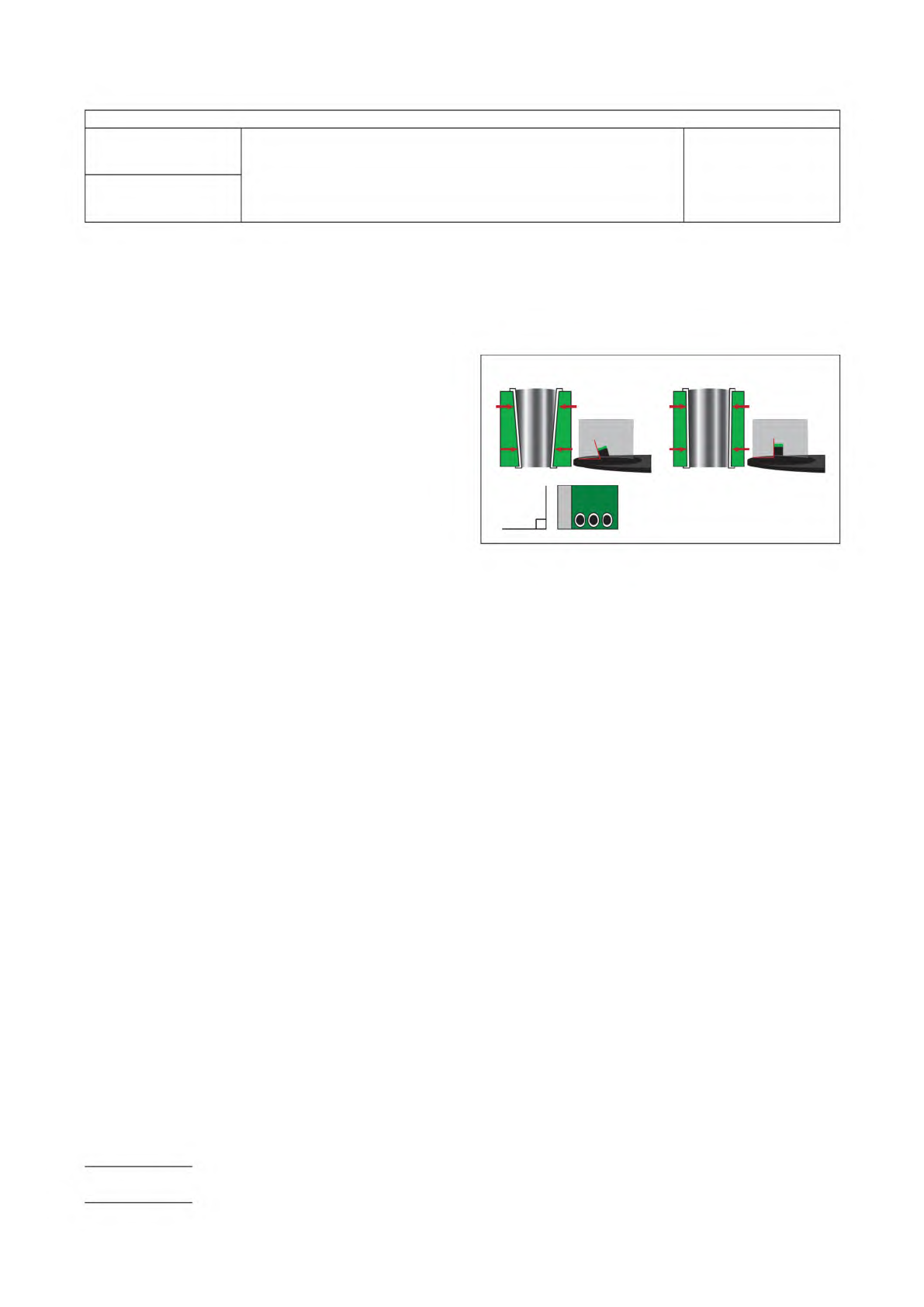
5.2.1 Method A
Deburr all edges prior to mounting using
rough grind grit in accordance with Table 5-1 to within
approximately 1.27 mm [0.05 in] of final polish depth. Ensure
that the evaluation edge is parallel to the mounting surface
and the sample maintains perpendicularity as shown in Figure
5-1.
5.2.2 Method B
Remove the specimen from the printed
board or panel such that the tooling pin holes or target PTHs
are not damaged.
5.2.2.1 Inspect Tooling Pin System
Inspect the tooling
pin holes or slots to verify they are not plugged or damaged.
Clear plugged tooling pin holes with a tool that will not change
its dimensional location or enlarge the hole. A drill bit of the
same hole diameter is recommended.
Inspect the tooling pins for foreign material adhering to them.
Clean the pin surface as required. Discard any pins that are
bent or the surface scarred.
5.3 Mounting Metallographic Sample
5.3.1
Clean mount molds and mounting surface and dry
thoroughly. Apply release agent (Optional).
5.3.2
Thoroughly clean the sample using a suitable solvent
such as isopropyl or ethyl alcohol. This is especially important
when flux or oil is present as it may result in poor adhesion of
the potting material causing gaps between the specimen and
the material. These gaps make proper metallographic sample
preparation extremely difficult, if not impossible.
5.3.3 Loading the Specimen
5.3.3.1 Method A
Stand specimen in mount mold, perpen-
dicular to the base using sample supports, clips, or with the
IPC-221-5-1
Figure 5-1 Maintaining Perpendicularity throughout the
Microsection Process
90º
NOT PERPENDICULAR PERPENDICULAR
IPC-TM-650
Number
2.1.1
Subject
Microsectioning, Manual and Semi or Automatic Method
Date
6/15
Revision
F
Page 2 of 8
000

use of double-sided adhesive tape. Keep sample in center of
mount mold.
5.3.3.2 Method B
Load specimen on tooling pins. The pins
align the target PTHs on a common plane. This common
plane assures all the PTHs will grind to the center of the hole
at the same instance.
Push the tooling pins into the tooling holes or slots. The pins
must fit snugly.
5.3.4 Preparing Potting Material
Personal protection is
recommended to prevent skin sensitization. Prepare potting
material to ensure cure temperature does not exceed 93 °C
[200 °F]. Mix by folding the potting material in such a way so
as to minimize air bubbles.
5.3.5 Pouring Potting Material
Fill the mount mold care-
fully with potting material, by pouring from one side to ensure
adhesion to all sample surfaces.
5.3.5.1 Method A
The sample must remain upright while
pouring.
5.3.5.2 Method B
Assure the tooling pins do not shift
position or rise up while pouring and/or curing of the potting
material.
5.3.6 Removal of Vacuum or Pressure for Potting Mate-
rials
While in a liquid state, potting materials may require
vacuum or pressure in order to achieve proper encapsulation.
Remove vacuum or pressure prior to cure to prevent undue
stress on the specimen.
5.3.7 Cure and Mount Removal
Allow specimen to cure
and cool to room temperature before removing hardened
mount from mount mold. The minimum qualities the mount
should exhibit are:
• The potting material is hard and not tacky.
• Minimal bubbles in the potting material.
• No gaps between the potting material and the sample.
• All gaps in structure to be evaluated should be filled with
potting material.
The presence of these deficiencies will result in sample prepa-
ration difficulties, as noted in 5.3.2.
5.3.8 Marking of Specimen
Identify the specimen by a
permanent method (see 4.22). The selected marking system
should remain unaffected by subsequent processing.
5.3.9 Mount Preparation
5.3.9.1 Method A
Remove sharp edges and flatten top
with low grit (240) sand paper.
5.3.9.2 Method B
Remove the excess mounting material
from the exposed ends of pins.
5.4 Grinding and Polishing
The following is a description
of the basic grinding and polishing steps. Other methods may
be required by contract. See Table 5-1 for examples of 2, 3,
4, and 5-step methods for Method A and Table 5-2 and Table
5-3 for Method B.
The minimum qualities the mount shall exhibit are:
1) The grinding and polishing accuracy of the microsection
shall be such that the viewing area of each of the PTHs is
within 10% of the drilled diameter of the hole as shown in
Figure 5-2.
2) Only fine grind scratches apparent on the mount when
viewed at 100X magnification.
3) Little or no gap between the potting material and the
specimen(s).
4) No residual abrasive paper grit material on the mount
surface.
5) The ground surface has only one plane of material removal.
If the mount has several planes of material removal, por-
tions of the sample will not polish since the odd surface
never touches the polishing cloth.
Note: Ultrasonic cleaning is highly recommended, especially
between the finer grinding steps, prior to rough polishing and
between all polishing steps. It is the nature of printed board
specimens, especially those with epoxy base material follow-
ing thermal exposures, to contain voids that can trap grinding
and polishing residues that are not removed during simple
rinsing. Care needs to be exercised not to damage the speci-
men surface with excessive ultrasonic cleaning. Specimen
sample can be placed with the polished surface perpendicu-
lar to the bottom of the vessel. Ultrasonic cleaning for as little
as one minute can damage a polished surface.
IPC-TM-650
Number
2.1.1
Subject
Microsectioning, Manual and Semi or Automatic Method
Date
6/15
Revision
F
Page 3 of 8