IPC-TM-650 EN 2022 试验方法--.pdf - 第82页
ASTM D-1210-79 *Source: Pr ecision Gage & T oo l Co. 2 8 Volkenand A ve., Dayton, Ohi o 45410 51 3/254-8404 T a ble 1 1st 4th Major T ype 1 160µm 150 µm 140 µ m T ype 2 80µm 75 µm 65 µm T ype 3 50µm 45 µm 40 µm T ype…
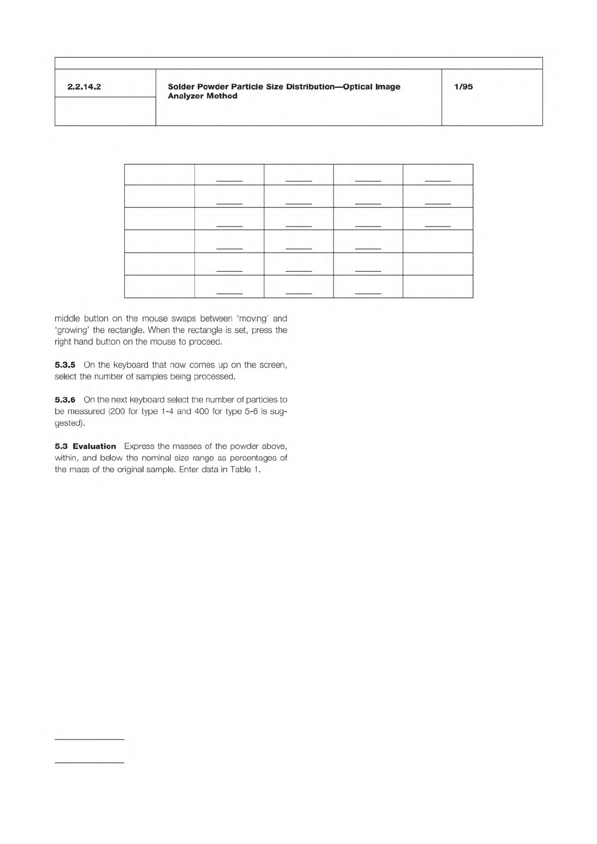
Table 1
Type 1 +150µm +75 µm +20 µm –20 µm
Type 2 + 75 µm +45 µm +20 µm –20 µm
Type 3 + 45 µm +25 µm +20 µm –20 µm
Type 4 + 38 µm +20 µm –20 µm
Type 5 + 30 µm +15 µm –15 µm
Type 6 + 15 µm + 5 µm – 5 µm
IPC-TM-650
Number
Subject Date
Revision
Page 2 of 2
2.2.14.2
Solder
Powder
Particle
Size
Distribution
—
Optical
Image
Analyzer
Method
1/95
middle
button
on
the
mouse
swaps
between
'moving'
and
'growing'
the
rectangle.
When
the
rectangle
is
set,
press
the
right
hand
button
on
the
mouse
to
proceed.
5.3.5
On
the
keyboard
that
now
comes
up
on
the
screen,
select
the
number
of
samples
being
processed.
5.3.6
On
the
next
keyboard
select
the
number
of
particles
to
be
measured
(200
for
type
1
-4
and
400
for
type
5-6
is
sug¬
gested).
5.3
Evaluation
Express
the
masses
of
the
powder
above,
within,
and
below
the
nominal
size
range
as
percentages
of
the
mass
of
the
original
sample.
Enter
data
in
Table
1.
ASTM D-1210-79
*Source: Precision Gage & Tool Co. 28 Volkenand Ave., Dayton, Ohio
45410 513/254-8404
Table 1
1st 4th Major
Type 1 160µm 150 µm 140 µm
Type 2 80µm 75 µm 65 µm
Type 3 50µm 45 µm 40 µm
Type 4 40µm 38 µm 35 µm
Type 5 30µm 25 µm 23 µm
Type 6 20µm 15 µm 15 µm
The Institute for Interconnecting and Packaging Electronic Circuits
2215 Sanders Road • Northbrook, IL 60062
Material in this Test Methods Manual was voluntarily established by Technical Committees of the IPC. This material is advisory only
and its use or adaptation is entirely voluntary. IPC disclaims all liability of any kind as to the use, application, or adaptation of this
material. Users are also wholly responsible for protecting themselves against all claims or liabilities for patent infringement.
Equipment referenced is for the convenience of the user and does not imply endorsement by the IPC.
Page 1 of 2
IPC-TM-650
TEST
METHODS
MANUAL
1
.0
Scope
This
test
method
is
designed
to
determine
the
maximum
(average)
solder
particle
size
in
a
solder
paste
using
a
fineness
of
grind
gauge.
2
.0
Applicable
Documents
Fineness
of
Dispersion
of
Pigment-Vehicle
Systems
3
.0
Test
Specimen
At
least
100
grams
of
uniformly
mixed
solder
paste.
4
.0
Equipment/Apparatus
Gauge-Hegman
Type
OMA
185*,
or
equivalent,
in
accordance
with
ASTM
D1
21
0-79.
A
hardened
steel,
stainless
steel,
or
chrome-
plated
steel
block
approximately
175
mm
in
length,
65
mm
in
width,
and
13
mm
thick.
The
top
surface
of
the
block
shall
be
ground
smooth
and
flat
and
shall
contain
one
or
two
grooves
140
mm
in
calibrated
length
and
12.5
mm
wide
parallel
to
the
longer
sides
of
the
block.
Each
groove
shall
be
tapered
uniformly
in
depth
lengthwise
from
a
suitable
depth
(for
example
50
to
1
00
micrometers)
at
1
0
mm
from
one
end
to
zero
depth
at
the
other
with
interme¬
diate
calibrations
in
accordance
with
the
depth
at
these
points.
Scraper
—
A
single-
or
double-edged
hardened
steel,
stainless
steel,
or
chrome-plated
steel
blade
90
mm
long,
38
mm
wide,
and
6.4
mm
thick.
The
edge
or
edges
on
the
long
sides
shall
be
straight
and
rounded
to
a
radius
of
approximately
0.38
mm.
Number
2.2.14.3
Subject
Determination
of
Maximum
Solder
Powder
Particle
Size
Date
Revision
1/95
Originating
Task
Group
Solder
Paste
Task
Group
(5-24b)
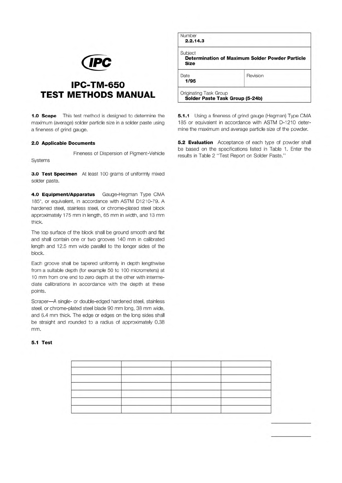
5.1.1
Using
a
fineness
of
grind
gauge
(Hegman)
Type
CMA
185
or
equivalent
in
accordance
with
ASTM
D-1210
deter¬
mine
the
maximum
and
average
particle
size
of
the
powder.
5.2
Evaluation
Acceptance
of
each
type
of
powder
shall
be
based
on
the
specifications
listed
in
Table
1.
Enter
the
results
in
Table
2
"Test
Report
on
Solder
Paste.”
5.1
Test
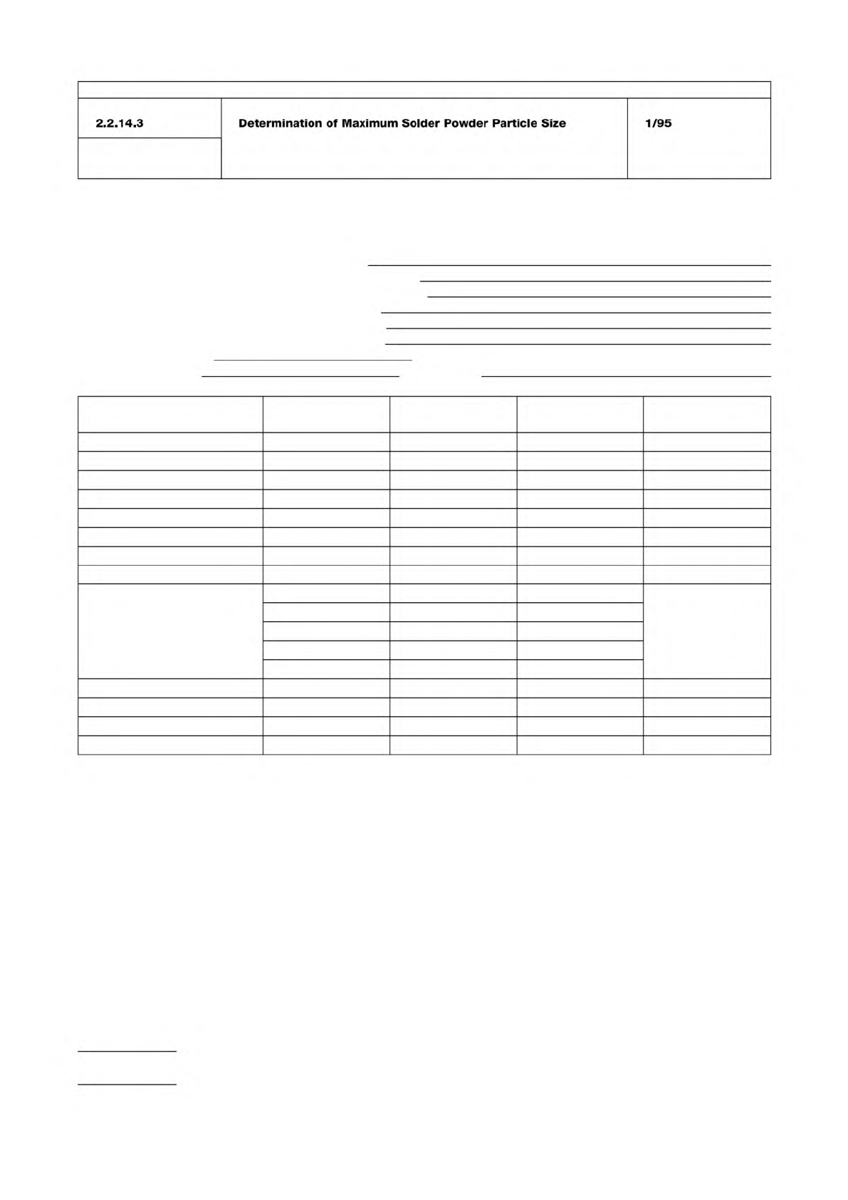
Table 2 Test Report on Solder Paste
Enter appropriate information in top portion of report and complete report by entering the test results or checkmarks in the appropriate spaces.
Inspection Purpose: QPL I.D. Number:
__ Qualification Manufacturer’s Identification:
__ Quality Conformance A Manufacturer’s Batch Number:
__ Quality Conformance B Date of Manufacture:
__ Shelf-Life Extension Original Use-By Date:
__ Performance Revised Use-By Date:
Date Inspection Completed: Overall Results: __ Pass __ Fail
Inspection Performed by:
Witnessed by:
Inspections
User’s Actual
Requirement Test Result P/F (*) Tested by & Date
Material
Visual
Metal Content
Viscosity
Solder Ball
Slump
Alloy
Flux
Powder Size
% In Top Screen
% In Next Screen
% In Bottom Screen
% In Receiver Bottom
Max. Powder Size
Powder Shape
Tack
Wetting
* P/F = PASS/FAIL; enter P if test results are within tolerance of actual requirement; otherwise, enter F
IPC-TM-650
Number
Subject Date
Revision
Page 2 of 2
2.2.14.3
Determination
of
Maximum
Solder
Powder
Particle
Size
1/95