IPC-TM-650 EN 2022 试验方法--.pdf - 第720页
5.5.6 Upon completion of the 168 hours, turn off the bias and open the test chamber and allow the test spe cim e ns to return to laboratory ambi ent conditions. 5.6 Cla ss H – Measurements/Evaluation 5. 6.1 Upo n sp ecim…

4.10 Flux
Water white rosin (R or RMA) with halide content
less than 0.5%, i.e., type Symbol A and B or ROL0 and ROL1
according to J-STD-004.
5 Test Conditions
5.1.1 Class T
85 ± 2 °C [185 ± 3.6 °F] with 85% relative
humidity minimum, 10 VDC bias, for 500 hours.
5.1.2 Class H
85 ± 2 °C [185 ± 3.6 °F] with 90, +5/-0%
relative humidity, 10 VDC bias for 168 hours.
5.2 Specimen Preparation
5.2.1
Positive, permanent and noncontaminating identifica-
tion of the test specimens is of paramount importance.
5.2.2
Visually inspect the test specimens for any obvious
defects, as described in IPC-A-600. If there is any doubt
about the overall quality of any test specimen, the test speci-
men should be discarded.
5.3 Electrical Connections (Both Classes)
5.3.1
For qualification testing, solder single strand PTFE
insulated wires or equivalent to the lands of each of the D test
patterns using a noncontact shield to protect the patterns
from flux splattering. These wires will be used to connect the
test specimen to the bias voltage or resistance meter. Test
points 1, 3 and 5 are to be connected to the positive terminal
and test points 2 and 4 are to the negative terminal of resis-
tance meter or power supply. When resistors are used, they
are to be connected between test points 1, 3 and 5 and the
positive terminal of power supply.
5.3.2
For conformance testing, solder single strand PTFE
insulated wires or equivalent in each of the connecting points
of the pattern described in 3.2 using a noncontact shield to
protect the patterns from flux splattering. These wires will be
used to connect the test specimen to the bias voltage or
resistance meter. One side of the pattern should be con-
nected to the positive terminal and the other side to the nega-
tive terminal of resistance meter or power supply. When resis-
tors are used, they are to be connected between the pattern
and the positive terminal of power supply.
5.3.3
The flux shall not be removed from the test speci-
mens.
5.4 Procedures
5.4.1 Desiccator Test Method
5.4.2
Take insulation resistance measurements of the test
specimens using 10 VDC, prior to testing. This step will
ensure that the resistance measurements are sufficient to pro-
ceed with testing.
5.4.3
Prepare a saturated solution of distilled water and
potassium sulfate (approximately 35g per 100 mL) at a tem-
perature of 85 °C [185 °F]. Pour the solution into the desicca-
tor just below the ceramic plate. Crystals of potassium sulfate
should remain visible in the saturated solution in the oven at
operating temperature.
5.4.4
Place the test specimens into the desiccator, such
that they do not touch one another. Route the connecting
wires to the outside of the desiccator and seal with a silicone
potting compound such as Dow Corning 732 RTV or a heat
resistant vacuum grease.
5.4.5
Place the desiccator into an oven maintained at 85 °C
[185 °F]. For the remaining test procedures, see 5.5.4 to 5.6.2
for Class H and 5.7.4 to 5.8.4 for Class T.
5.5 Class H – Test Chamber Method
5.5.1
Prior to testing, take insulation resistance measure-
ments of the test specimens using 10 VDC. This step will
ensure that the resistance measurements are sufficient to pro-
ceed with testing.
5.5.2
Place the specimens into the test chamber and route
the wires through the porthole of the test chamber and seal, if
necessary.
5.5.3
Set the chamber’s parameters, which is a noncon-
densing ramp, for 85 °C [185 °F] with 90% relative humidity.
Close the chamber doors and activate the test chamber.
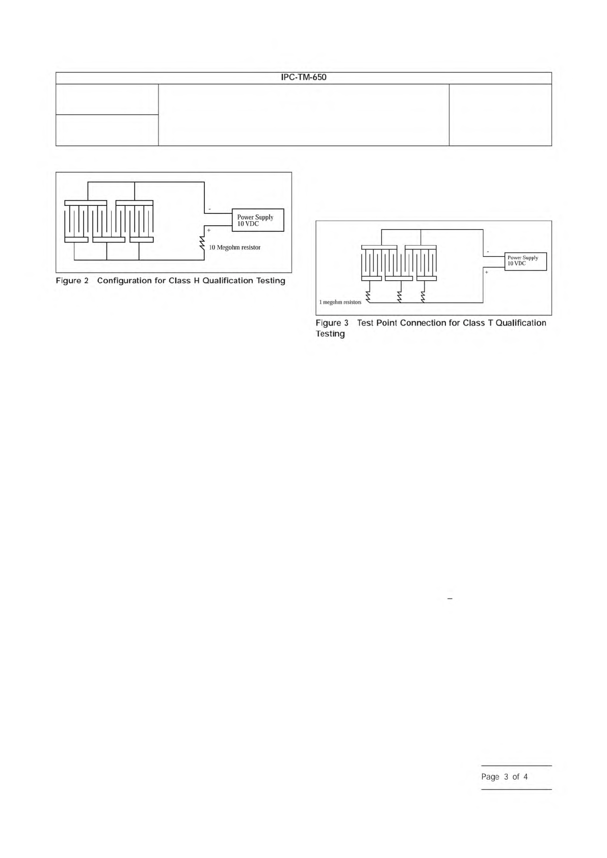
5.5.4
Connect the correct test points as specified in 5.3.1
and 5.3.2 to a 10-megohm resistor before the positive termi-
nal of power supply. (See Figure 2 for configuration for quali-
fication testing.) Apply the bias voltage of 10 VDC.
5.5.5
Allow the test specimens to remain in the test cham-
ber for the duration of 168 hours (seven days).
Number
2.6.14
Subject
Solder Mask - Resistance to Electrochemical Migration
Date
03/07
Revision
D
IPC-TM-650
Page
2
of
4
5.5.6
Upon completion of the 168 hours, turn off the bias
and open the test chamber and allow the test specimens to
return to laboratory ambient conditions.
5.6 Class H – Measurements/Evaluation
5.6.1
Upon specimen stabilization at laboratory ambient
temperature, take the resistance measurements, as specified
in 5.5.1, with 10 VDC and record.
5.6.2
Examine the test specimens with 10X magnification
with backlighting for electrochemical migration.
5.7 Class T – Test Chamber Method
5.7.1
Prior to testing, take insulation resistance measure-
ments of the test specimens using 45 -100 VDC. This step will
ensure that the resistance measurements are sufficient to pro-
ceed with testing.
5.7.2
Place the test specimens into the test chamber and
route the wires through the porthole of the test chamber and
seal, if necessary.
5.7.3
Set the chamber’s parameters for 85 °C [185 °F] with
85% relative humidity minimum. Close the chamber doors and
activate the test chamber.
5.7.4
Allow the test specimens to stabilize at test conditions
for 96 hours (four days).
5.7.5
After the 96-hour (four days) stabilization period at test
conditions, take measurements of initial insulation resistance
as specified in 5.7.1 with 45 -100 VDC.
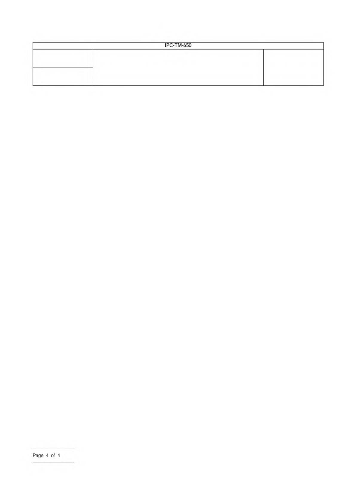
5.7.6
After obtaining the measurements, connect each test
point as specified in 5.3.1 and 5.3.2 to a 1-megohm resistor
before the positive terminal of power supply. (See Figure 3 for
configuration of qualification testing.) Apply the bias voltage of
10VDC. The test polarity shall be the same as the measure-
ment polarity stated in 5.7.1.
5.7.7
Allow the specimens to remain in the test chamber an
additional 404 hours (500 hours total test time).
5.8 Class T – Measurements/Evaluations
5.8.1
Upon completion of the 500 hours (21 days), discon-
nect the power supply and repeat the measurements as
stated in 5.7.5 with the specimens under test conditions.
5.8.2
The chamber is then turned off and the specimens are
removed from the test chamber and visually inspected with
backlighting at 10X magnification for electrochemical migra-
tion.
5.8.3
The individual resistance measurements obtained at
96 hours and 500 hours shall be averaged using the following
calculation. These initial and final average insulation resistance
readings shall then be reported.
IR
avg
= 10
[
1
N
Σ
1
N
log IR
i
]
Where:
N = Number of test points (12 nominal)
IR
i
= Individual insulation resistance measurements
5.8.4
Where an assignable cause can be found, exception-
ally low insulation resistance readings can be excluded from
calculating the average value, provided that 11 (of the original
12) measurements are included in the average. Such assign-
able causes are attributable to the laminate itself or to the
process used to produce the printed board. They include:
IPC-2614-2
IPC-2614-3
Number
2.6.14
Subject
Solder Mask - Resistance to Electrochemical Migration
Date
03/07
Revision
D
IPC-TM-650
10
Megohm
resistor
Power
Supply
10VDC
Figure
2
Configuration
for
Class
H
Qualification
Testing
1
megohm
resistors
Power
Supply
10VDC
Figure
3
Test
Point
Connection
for
Class
T
Qualification
Testing
Page
3
of
4
a. Contamination on the insulating surface of the board such
as lint, solder splines, or water droplets from the condition-
ing chamber.
b. Incompletely etched patterns that decrease the insulating
space between conductors by more than the amount
allowed in the appropriate design requirements drawing.
c. Scratched, cracked or obviously damaged insulation
between conductors.
6 Notes
6.1
Protective coatings are helpful in preventing electro-
chemical migration, but there is no assurance that the protec-
tion is complete unless the coating is adequately bonded to a
good clean board.
Number
2.6.14
Subject
Solder Mask - Resistance to Electrochemical Migration
Date
03/07
Revision
D
IPC-TM-650
Page
4
of
4