IPC-TM-650 EN 2022 试验方法--.pdf - 第253页
/ Figure 3 Chain to Hemostat A dapter IPC-TM-650 Number Subject Date Revision Page 3 of 3 2.4.8.1 Peel Strength, Metal Foil (Keyhole Method For Thin Laminates) 1/86 5.4 Evaluation 5.4.1 Calculate the peel strength per mm…
Figure
2 Keyhold Horizontal Axis
10 cm ±
0.25 cm
(2) .138-32UN-2B
0.025 cm dia.
0.064 cm
± 0.05 cm
10 cm ± 0.25 cm
0.475 cm
± 0.025 cm
0.95 cm ±
0.025 cm
2
0.064 cm
AL Alloy
0.475 cm
± 0.05 cm
0.95 cm ± 0.075 cm
3
MS 16995
SCR CAP SOC HD
10.5 cm
± 0.075 cm
AA6061 T651
0.475 cm
± 0.025 cm
1.9 cm
± 0.025 cm
0.4 cm
+ 0.013 cm
- 0.0075 cm
dia.
2 holes
0.32 cm thick
AL Alloy
AA6061 T651
1
GI
IPC-TM-650
Number
Subject Date
Revision
Page 2 of 3
2.4.8.1
Peel
Strength,
Metal
Foil
(Keyhole
Method
For
Thin
Laminates)
1/86
I
PC-2-4-8-1
-2
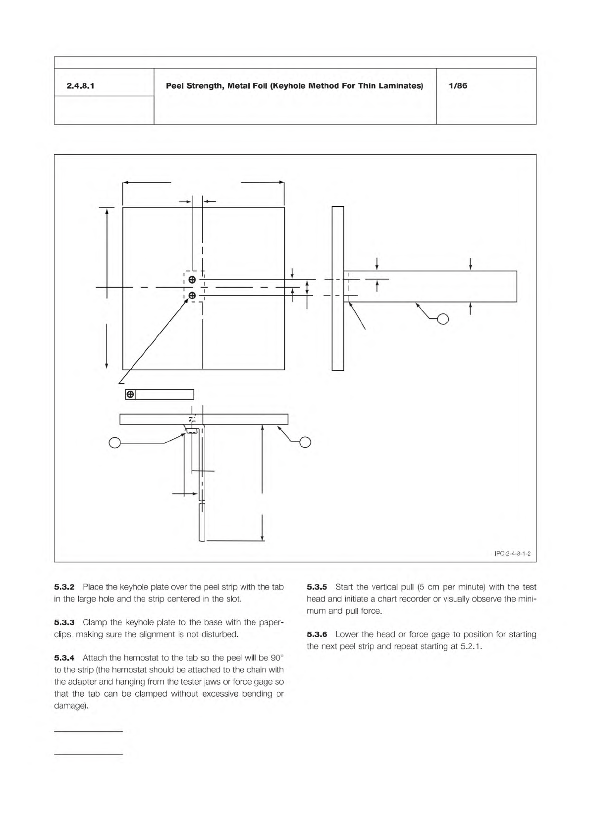
5.3.2
Place
the
keyhole
plate
over
the
peel
strip
with
the
tab
in
the
large
hole
and
the
strip
centered
in
the
slot.
5.3.3
Clamp
the
keyhole
plate
to
the
base
with
the
paper¬
clips,
making
sure
the
alignment
is
not
disturbed.
5.3.4
Attach
the
hemostat
to
the
tab
so
the
peel
will
be
90°
to
the
strip
(the
hemostat
should
be
attached
to
the
chain
with
the
adapter
and
hanging
from
the
tester
jaws
or
force
gage
so
that
the
tab
can
be
clamped
without
excessive
bending
or
damage).
5.3.5
Start
the
vertical
pull
(5
cm
per
minute)
with
the
test
head
and
initiate
a
chart
recorder
or
visually
observe
the
mini¬
mum
and
pull
force.
5.3.6
Lower
the
head
or
force
gage
to
position
for
starting
the
next
peel
strip
and
repeat
starting
at
5.2.1.

/
Figure 3 Chain to Hemostat Adapter
IPC-TM-650
Number
Subject Date
Revision
Page 3 of 3
2.4.8.1
Peel
Strength,
Metal
Foil
(Keyhole
Method
For
Thin
Laminates)
1/86
5.4
Evaluation
5.4.1
Calculate
the
peel
strength
per
mm
of
width
by
mea¬
suring
the
strip
width
in
mm,
using
the
following
formula:
1
mm
—
—
x
observed
pull
force
=
measured
strip
width
in
mm
peel
strength
mm
width
6
Notes
6.1
Peel
strength
is
usually
the
minimum
peel
strength
observed.
IPC-TM-650 Test Methods Manual
The Institute for Interconnecting and Packaging Electronic Circuits
2215 Sanders Road • Northbrook, IL 60062-6135
Material in this Test Methods Manual was voluntarily established by Technical Committees of the IPC. This material is advisory only
and its use or adaptation is entirely voluntary. IPC disclaims all liability of any kind as to the use, application, or adaptation of this
material. Users are also wholly responsible for protecting themselves against all claims or liabilities for patent infringement.
Equipment referenced is for the convenience of the user and does not imply endorsement by the IPC.
Page 1 of 3
IPC-TM-650
TEST
METHODS
MANUAL
1
.0
Scope
The
purpose
of
this
test
is
to
determine
the
peel
strength
of
metal
cladding
to
the
base
laminate
while
at
elevated
temperature;
and
to
evaluate
the
base
laminate
material
after
the
peel
strength
test
is
completed
for
degrada¬
tion
due
to
the
conditioning.
2
.0
Applicable
Documents
Method
2.4.8.
1
,
Peel
Strength,
Metal
Foil
(Keyhole
Method
for
Thin
Laminates)
Method
5.8.3,
Peel
Strength
Test
Pattern
3
.0
Test
Specimens
3.1
Size
and
Configuration
Specimens
shall
be
50.8
mm
x
50.8
mm
[2.0
x
2.0
in]
by
the
thickness
of
the
laminate.
Cladding
test
strips
shall
be
as
specified
(see
5.1
.2).
3.2
Quantity
and
Sampling
Unless
otherwise
specified,
specimens
shall
be
one
lengthwise
for
each
clad
side
and
one
crosswise
for
each
clad
side.
The
outside
25.4
mm
[1
in]
bor¬
der
of
the
parent
sheet
or
panel
shall
be
excluded.
4
.0
Apparatus
or
Material
4.1
Tensile
Tester
A
tensile
strength
tester
equipped
with
a
load
cell,
capable
of
measuring
to
the
nearest
0.0045
kg
[0.01
lbs.]
and
a
light
load
wire
or
chain
and
clamp
at
least
457
mm
[18
in]
long
(its
weight
is
included
in
the
load
cell
cal¬
culation).
The
clamp
jaws
must
cover
the
entire
width
of
each
peel
strip
tab.
Any
equipment
or
apparatus
having
the
described
accuracy,
precision,
and
reproducibility
may
be
used.
4.2
Hot
Fluid
Bath
A
fluid
bath
or
pot
capable
of
maintain¬
ing
the
specified
fluid
at
the
specified
temperature
when
mea¬
sured
2.54
mm
[1
.0
in]
below
the
surface.
4.2.1
Dow
Silicone
Fluid
No.
704,
or
equivalent.
4.3
Specimen
Hold-down
A
suitable
hold-down
clamping
system
equivalent
in
performance
as
that
defined
in
IPC-TM-
650,
Method
2.4.
8.1.
Number
2.4.8.2
Subject
Peel
Strength
of
Metallic
Clad
Laminates
at
Elevated
Temperature
(Hot
Fluid
Method)
Date
Revision
12/94
A
Originating
Task
Group
MIL-P-13949
Test
Methods
Task
Group
(7-1
1b)
4.4
Data
Collection
For
qualification
testing,
a
recording
system
capable
of
permanent
data
retention
incorporated
into
the
test
apparatus.
4.5
Measuring
device
capable
of
measuring
from
0.000
to
12.7
mm
[0.500
in]
to
within
±
0.0025
mm
[0.0001
in].
4.6
Etch
Resist
Materials
or
Systems
4.6.1
Plater's
tape,
or
equivalent,
to
act
as
etch
resist
for
strip
formation
of
the
specified
widths
(see
3.3
and
3.4).
4.6.2
Photoresist
system
(printing,
developing,
and
strip¬
ping).
4.7
Etching
system
capable
of
complete
removal
of
metallic
cladding.
4.8
Circulating
air
oven
capable
of
maintaining
125
土
2
℃
[257
±
3.6°F].
5
.0
Procedure
5.1
Specimen
Preparation
5.1.1
Cut
the
specimens
from
the
laminate
sample.
Speci¬
mens
shall
be
taken
no
closer
than
2.54
mm
[1
.0
in]
from
the
edge
of
the
laminate
sheet
as
manufactured.
5.1.2
Specimens
shall
be
prepared
with
at
least
four
resist
strips
of
3.18
mm
[0.125
in]
width
and
then
etched,
cleaned
and
processed
using
standard
industry
practices
and
equip¬
ment.
For
qualification
and
referee
testing
the
specimen
shall
be
photoimaged
in
accordance
with
the
artwork
shown
in
Method
5.8.3
of
IPC-TM-650
and
reproduced
here
as
Figure
1
,
except
that
tab
ends
are
optional.
Specimens
shall
be
etched
so
that
the
conductor
strips
on
one
specimen
are
in
one
direction
per
Figure
1
.
Double
clad
laminate
shall
have
each
side
tested
using
separate
specimens.
The
opposite
side
cladding
shall
be
either
fully
removed
or
left
fully
clad.
Separate
specimens
for
both
the
warp
and
fill
directions
are
required
for
each
side.
For
referee
testing
the
cladding
on
the
opposite
side
shall
remain.