IPC-TM-650 EN 2022 试验方法--.pdf - 第663页
5.8.3 Cl ass T Evaluation 5.8.3.1 Three separa te se ts of m easurem ents are to be recorded for the uncoated specimen, the ‘as received’ speci- men, and the specimen afte r solder exposure. Each set of readings shall be…
b. Maintain temperature at 65 ± 2 °C [149 ± 3.6 °F] for 3,
+0.5/-0 hours
c. Lower the temperature from 65 ± 2 °C [149 ± 3.6 °F] to
25 ± 2 °C [77 ± 3.6 °F] over a time span of 2.5 hours ± 5
minutes
There shall be no delay between cycles.
5.7.2 Class H Measurement
5.7.2.1
Disconnect the 50 VDC bias voltage source before
taking the insulation resistance measurements. Electrical con-
nections to specimens shall be made such that the bias and
test voltages are of the same polarity. Insulation resistance
shall be read as specified in 5.7.1.4. Apply 100 VDC on the
specimens test points with the resistance meter and take the
reading after one minute with the patterns under test condi-
tions.
5.7.2.2
For qualification testing, measure and record resis-
tance once every 24 hours (if insulation resistance quality
measurements are required, see 5.7.3.1), between the 2nd
and 3rd hour of the high termperature phase of each cycle.
These measurements are to be conducted without opening
the chamber. After completion of the temperature cycling, dis-
connect the bias voltage, remove the specimens from the
chamber, and measure and record insulation resistance after
the specimen has been at ambient conditions for more than
one hour but less than two hours.
5.7.2.3
For conformance testing using pattern C, the mea-
surements should be taken after disconnectng the bias volt-
age, removing the specimens from the test chamber and
allowing the specimens to stabilize to laboratory ambient con-
ditions for one hour and not exceeding two hours. See 6.2.
5.7.3 Class H Evaluation
5.7.3.1
Each test specimen shall be evaluated for insulation
resistance quality following and/or during the stated condi-
tions. Although several insulation resistance readings may be
taken during the test, only the final (18th cycle) readings in
high temperature phase in the chamber and the reading taken
outside the chamber shall be used to determine pass/fail cri-
teria.
5.7.3.2
After completion of all electrical testing, the test
specimens shall be examined for blisters or delamination fol-
lowing the 24-hour stabilization at ambient laboratory condi-
tions. See 6.2.
5.8 Class T Procedures
5.8.1 Class T Testing
5.8.1.1
Condition the specimens at 50 ± 2 °C [122 ± 3.6 °F]
with no added humidity, for a period of 24 hours.
5.8.1.2
Remove the specimens from the oven and cool to
laboratory ambient temperature. Apply 100 VDC to comb pat-
terns E and F of each test specimen. See 6.2.
5.8.1.3
The test points for qualification are at each pair of
terminals (finger tabs) on the E and F comb patterns. One of
the test points is connected to the negative terminal and the
other to the positive terminal. For quality conformance, the
pair of test points is 1 to 2 on the C pattern. One side of the
C pattern should be connected to the negative terminal and
the other side to the positive.
5.8.1.4
Place the specimens in the test chamber in the ver-
tical position and under a condensation drip shield.
Each chamber load shall contain at least one
uncoated board that is representative of the cleaning process
used prior to solder mask application for each solder mask
tested.
5.8.1.5
Close the chamber door and bring the chamber to
65 ± 2 °C [149 ± 3.6 °F] and 90% relative humidity.
5.8.1.6
Allow specimens to stabilize at test conditions for 24
hours.
5.8.2 Class T Measurement
5.8.2.1
Connect the resistance meter to the appropriate test
points. For qualification testing, one of the test points of the
two terminal E and F patterns are connected to the negative
terminal and the other test point to the positive. For quality
conformance testing, one side of the C pattern (‘‘Y’’ pattern)
should be connected to the negative terminal and the other
side to the positive.
5.8.2.2
Apply 100 VDC on the specimens test points with
the resistance meter and take the reading after one minute
with the patterns under test conditions.
Number
2.6.3.1
Subject
Solder Mask - Moisture and Insulation Resistance
Date
03/07
Revision
E
IPC-TM-650
—
Note:
NOTE:
Other
readings
are
optional
and
may
be
used
for
diagnostic
information
or
aborting
the
test.
Page
4
of
5
5.8.3 Class T Evaluation
5.8.3.1
Three separate sets of measurements are to be
recorded for the uncoated specimen, the ‘as received’ speci-
men, and the specimen after solder exposure. Each set of
readings shall be averaged and shall be greater than the mini-
mum listed in the relevant specification. No individual insula-
tion resistance (IR) value may be less than 0.1 x IR
min
, where
IR
min
is the minimum in the set of IR values measured. Two
measurements may be excluded from calculating the average
if there is an assignable cause of low insulation resistance that
can be attributable to the laminate itself or to the process
used to produce the board. Such assignable causes include
but are not limited to:
a. Contamination of the insulating surface of the board such
as lint, solder splines, or water droplets from the condition-
ing chamber.
b. Incompletely etched patterns that decrease the insulating
space between conductors by more than the amount
allowed in the appropriate design requirements drawing.
c. Scratched, cracked or obviously damaged insulation
between conductors.
5.8.3.2
The average insulation resistance (IRavg) is calcu-
lated from:
IR
avg
= 10
[
1
N
Σ
1
N
log IR
i
]
Where:
N = Number of test points (12 nominal)
IR
i
= Individual insulation resistance measurements.
5.8.3.3
After completion of all electrical testing and following
the nominal 24-hour stabilization at laboratory ambient tem-
peratures (see 5.8.1.6), the test specimens shall be examined
for mealing, blisters, delamination or other forms of degrada-
tion.
6 Notes
6.1
Initial wire placement must be maintained to ensure
reproducible results.
6.2
Specimens may be stabilized at ambient conditions
specified, inside the chamber.
Number
2.6.3.1
Subject
Solder Mask - Moisture and Insulation Resistance
Date
03/07
Revision
E
IPC-TM-650
Page
5
of
5
1 Scope
This test method defines the procedures for deter-
mining the surface insulation resistance of a copper foil clad
flexible dielectric material in the presence of moisture. This
test method may be used for testing both metal clad dielec-
tric as produced per IPC-4204 and bondply dielectric that
must be evaluated for surface insulation resistance in a lami-
nated format as metal clad dielectric.
The moisture resistance test is performed for the purpose of
evaluating, in an accelerated manner, the resistance of mate-
rials to the deleterious effects of high humidity and heat con-
ditions. The test method is designed to simultaneously assess
leakage current caused by ionized water films and electro-
chemical degradation (corrosion and dendritic growth) of the
test vehicle.
2 Applicable Documents
2.1 IPC
Acceptability Guidelines
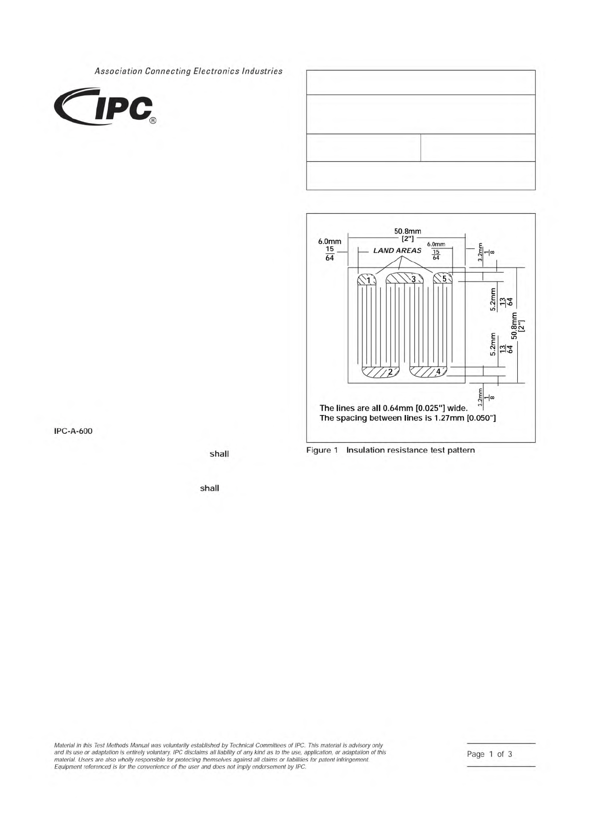
3 Test Specimen
The test specimen consist of an
etched conductor pattern in accordance with Figure 1. Test a
minimum of three test specimens per clad side. For double
clad material, a separate sample unit
be prepared for
each side.
3.1
The test points for comb patterns are 1 to 2, 2 to 3, 3 to
4, and 4 to 5. Test points 1-3-5 are connected to the positive
(+) terminal, and test points 2-4 are connected to the negative
(-) terminals of the resistance meter.
4 Apparatus
4.1 Test Chamber
A test chamber capable of producing
and recording an environment of 65 °C ± 2 °C [149 °F ±
3.6 °F] and 85% - 93% relative humidity and which will allow
the insulation resistance to be measured while the specimens
are under the specified conditions. This chamber is to be used
for static insulation resistance testing, involving a single tem-
perature and relative humidity to stress the test specimen over
the specified test time.
4.2 Power Supply
A power supply capable of producing a
bias potential of 100 volts dc with a tolerance of ± 10%.
4.3 Resistance Meter
A resistance meter capable of read-
ing 10
12
ohms or greater, with a measurement error not to
exceed 10%, with a test voltage of 500 volts dc.
4.4 Other Equipment or Materials
4.4.1
Soft bristle brush.
4.4.2
Deionized or distilled water (2 megohm cm minimum
resistivity recommended).
4.4.3
Isopropyl alcohol.
4.4.4
Single-stranded* PTFE or other fluorocarbon insulated
wire. (Shielded wire recommended.) [*single-stranded mini-
mizes flux wicking]
4.4.5
Soldering iron (25 - 40 watts).
4.4.6
Drying oven capable of maintaining at least 60 °C.
IPC-2632-1
▼
▼
▼
▼
▼
▼
▼
▼
▼
▼
▼
▼
▼
▼
▼
▼
▼
▼
▼
3000 Lakeside Drive, Suite 105N
Bannockburn, IL 60015-1249
IPC-TM-650
TEST METHODS MANUAL
Number
2.6.3.2
Subject
Surface Insulation and Moisture Resistance,
Copper Clad Flexible Dielectric Material
Date
8/14/15
Revision
C
Originating Task Group
D-15
Association
Connecting
Electronics
Industries
6.0mm
—
LAND
AREAS
0.050"]
6.0mm
15
__
64
all
0.64mm
[0.025"]
wide,
between
lines
is
1.27mm
50.8mm
The
lines
are
The
spacing
IPC-A-600
shall
shall
Figure
1
Insulation
resistance
test
pattern
Material
/n
this
Test
Methods
Manual
was
voluntarily
established
by
Technical
Committees
of
I
PC.
This
material
/s
advisory
only
and
"s
use
or
adaptation
,
s
entirely
voluntary.
IPC
disclaims
all
liability
of
any
kind
as
to
the
use,
application,
or
adaptation
of
this
material.
Users
are
also
wholly
responsible
for
protecting
themselves
against
all
claims
or
liabilities
for
patent
infringement.
Equipment
referenced
is
for
the
convenience
of
the
user
and
does
not
imply
endorsement
by
IPC.
Page
1
of
3
5
4
EEZE
J
EE8.09
EE^
EE^