IPC-TM-650 EN 2022 试验方法--.pdf - 第334页
J-STD-006 The Institute for Int erconnecting and Packaging E lectronic Circuits 2215 S anders Road • Northbrook, IL 60062-6135 Material in this T est M ethods Manual was voluntarily establis hed by T echni cal Committees…

IPC-TM-650
Number
Subject Date
Revision
Page 3 of 2
2.4.47
Flux
Residue
Dryness
1/95
6.0
Notes
6.1
Safety
Observe
all
appropriate
precautions
on
MSDS
for
chemicals
involved
in
this
test
method.
J-STD-006
The Institute for Interconnecting and Packaging Electronic Circuits
2215 Sanders Road • Northbrook, IL 60062-6135
Material in this Test Methods Manual was voluntarily established by Technical Committees of the IPC. This material is advisory only
and its use or adaptation is entirely voluntary. IPC disclaims all liability of any kind as to the use, application, or adaptation of this
material. Users are also wholly responsible for protecting themselves against all claims or liabilities for patent infringement.
Equipment referenced is for the convenience of the user and does not imply endorsement by the IPC.
Page 1 of 2
IPC-TM-650
TEST
METHODS
MANUAL
1
.0
Scope
This
test
method
provides
a
measurement
of
the
spitting
characteristics
of
flux-cored
wire
and
ribbon
sol¬
der.
2
.0
Applicable
Documents
Requirements
and
Test
Methods
for
Electronic
Grade
Solder
Alloys
and
Fluxed
and
Non-fluxed
Solid
Solders
for
Electronic
Soldering
Applications
3
.0
Test
Specimen
One
five
meter
length
of
the
J
-STD-
006
flux-cored
wire
or
ribbon
solder
(may
be
cut
into
several
smaller
lengths
for
convenient
handling).
4
.0
Apparatus
4.1
One
laboratory
stand
with
soldering
iron
support
clamp
and
metal
support
ring
or
tray
with
a
suitable
hole
in
center.
4.2
One
20
by
20
cm
piece
of
aluminum
foil
with
1
1
±
0.5
mm
diameter
hole
in
center.
4.3
One
small
metal
tray
with
suitable
hole
in
center,
for
catching
molten
solder
running
down
off
of
the
soldering
iron
tip.
4.4
One
soldering
iron
with
a
clean
chisel
point
which
has
been
coated
with
solder
and
wiped
clean.
5
.0
Test
Procedure
5.1
Preparation
for
Test
5.1.1
Using
additional
pieces
of
solder
identical
to
the
test
specimen,
determine
the
flux
content
of
the
flux
cored
solder
in
accordance
with
IPC-TM-650,
Test
Method
2.3.34.1
and
expressed
in
percentage
units
(%F).
5.1.2
Set
up
test
configuration
as
shown
in
figure
1
.
The
soldering
iron
should
be
positioned
so
that
its
tip
extends
approximately
6
mm
through
the
aluminum
foil.
Number
2.4.48
Subject
Spitting
of
Flux-Cored
Wire
Solder
Date
Revision
1/95
Originating
Task
Group
Solder
Alloy
Task
Group
(5-24c)
5.1.4
Weight
the
solder
sample
(W1).
5.1
.5
Turn
on
soldering
iron
and
allow
the
tip
temperature
to
stabilize.
5.2
Test
5.2.1
Apply
the
solder
sample
to
the
heated
soldering
iron
tip
approximately
at
an
even
rate,
1
cm
at
a
time,
keeping
the
soldering
iron
tip
temperature
steady.
5.3
Evaluation
5.3.1
Weight
the
stub(s)
of
the
solder
specimen
not
melted
in
the
test
(W2).
5.3.2
Weight
the
aluminum
foil
containing
the
spattered
flux
(P2).
5.3.3
Calculate
the
percent
weight
of
spattered
flux
as
fol¬
lows:
Percent
by
weight
of
spattered
flux
二
(P2-P1)
F
x
(W1
-
W2)
6
.0
Notes
6・1
Safety
Observe
all
appropriate
safety
precautions.
5.1.3
Weight
the
aluminum
foil
(P1)
and
place
it
on
the
labo¬
ratory
stand
tray/ring
so
that
the
11
mm
hole
is
centered
around
the
tip
of
the
soldering
iron.
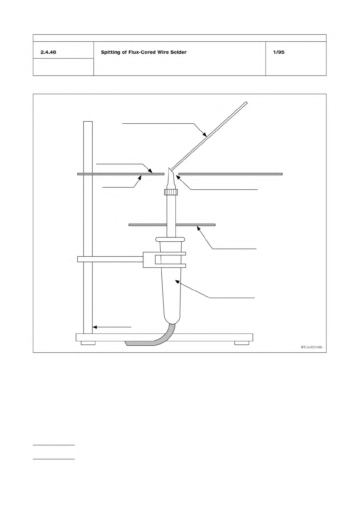
Figure 1 Test apparatus for spitting test
Stand
Soldering Iron
Metal tray to
collect solder
Hole 11mm Diameter
45°
Metal tray
Aluminum Foil
Flux Cored Solder Wire
IPC-TM-650
Number
Subject Date
Revision
Page 2 of 2
IPC-l-003166-