IPC-TM-650 EN 2022 试验方法--.pdf - 第479页
Step 1 – Step 2 – Step 3 – Step 4 – Step 1 – Step 2 – Step 3 – Step 4 – Figure 5-6 Measurement of Incident Step Amplitude TIME TDR INSTRUMENT SPD TRANSFER STANDARD V tran,0 V open V i,0 MEASUREMENT ZONE for TRANSMISSION …
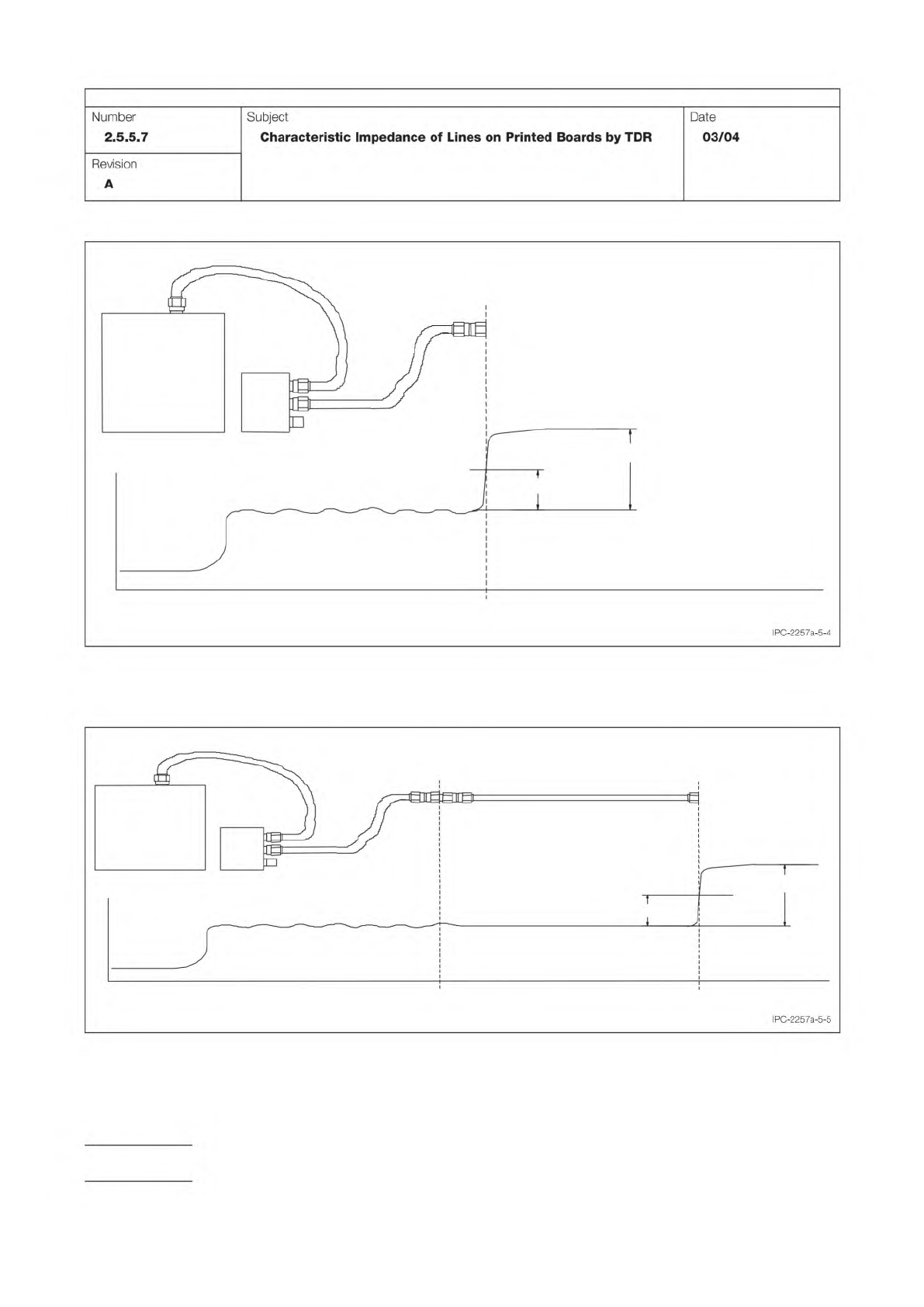
Figure 5-4 Determination of instant in the TDR waveform corresponding to the beginning of the reference line. A
R,0
is the
amplitude of the signal reflected from the open end of rf cable.
SPD
TDR
INSTRUMENT
PRECISION
RF CABLE
t
1,Ref
TIME
0.5
A
R.0
A
R,0
Figure 5-5 Determination of instant in TDR waveform corresponding to the end of the reference line (transfer standard or
air line reference).
A
R,0
is the amplitude of the signal reflected from the open end of the reference line.
SPD
TDR
INSTRUMENT
PRECISION
RF CABLE
t
1,Ref
TIME
0.5
A
R,0
A
R,0
REFERENCE LINE
t
2,Ref
IPC-TM-650
Page 10 of 23
Number
2.5.5.7
Subject
Characteristic
Impedance
of
Lines
on
Printed
Boards
by
TDR
Date
03/04
Revision
A
Step 1 –
Step 2 –
Step 3 –
Step 4 –
Step 1 –
Step 2 –
Step 3 –
Step 4 –
Figure 5-6 Measurement of Incident Step Amplitude
TIME
TDR
INSTRUMENT
SPD
TRANSFER
STANDARD
V
tran,0
V
open
V
i,0
MEASUREMENT ZONE
for TRANSMISSION LINE UNDER TEST
PRECISION
RF CABLE
t
i,TL
t
f,TL
MEASUREMENT ZONE
for REFERENCE LINE
t
i,Ref
t
f,Ref
IPC-TM-650
Page 11 of 23
Number
2.5.5.7
Subject
Characteristic
Impedance
of
Lines
on
Printed
Boards
by
TDR
Date
03/04
Revision
A
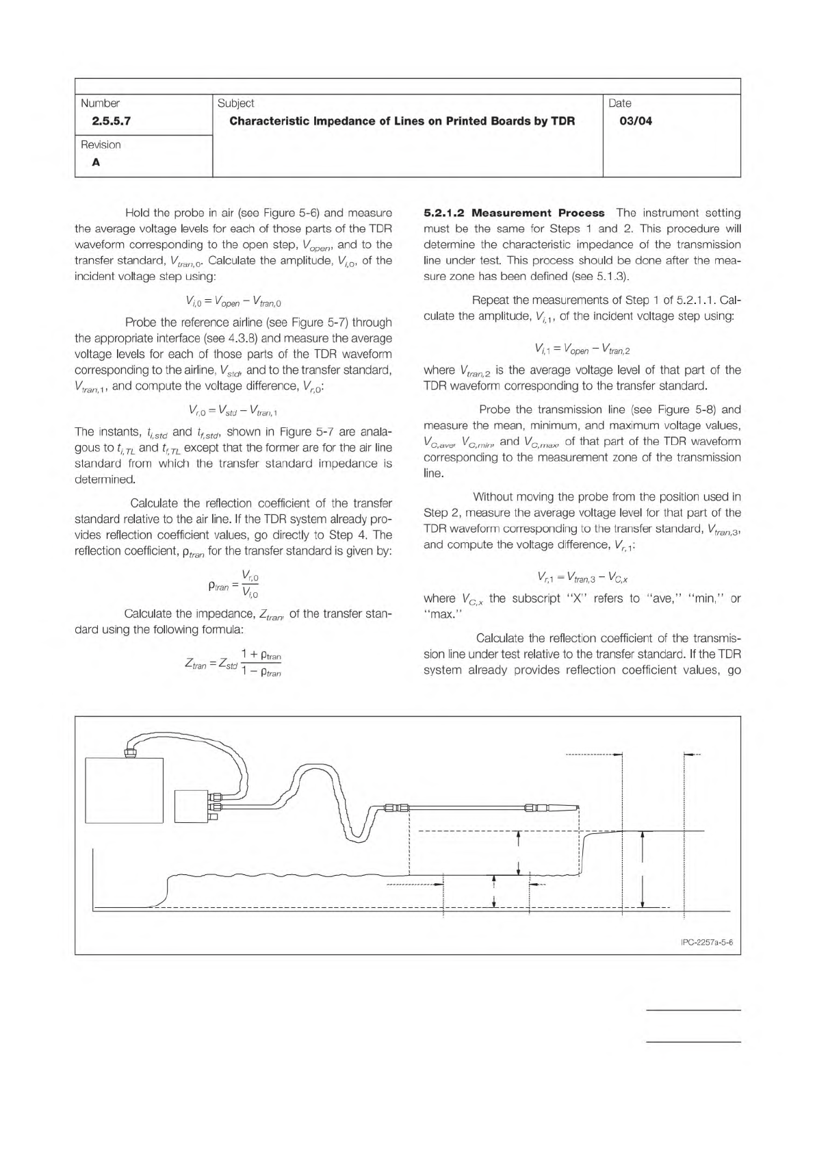
Hold
the
probe
in
air
(see
Figure
5-6)
and
measure
the
average
voltage
levels
for
each
of
those
parts
of
the
TDR
waveform
corresponding
to
the
open
step,
Vopen,
and
to
the
transfer
standard,
Vtran
0.
Calculate
the
amplitude,
Vi0,
of
the
incident
voltage
step
using:
二
Vopen
—
%rac,0
Probe
the
reference
airline
(see
Figure
5-7)
through
the
appropriate
interface
(see
4.3.8)
and
measure
the
average
voltage
levels
for
each
of
those
parts
of
the
TDR
waveform
corresponding
to
the
airline,
Vstd,
and
to
the
transfer
standard,
%c,i,
and
compute
the
voltage
difference,
Vr0:
%0
=
Vstd
-
Vtran,1
The
instants,
ti>std
and
tfstd,
shown
in
Figure
5-7
are
anala-
gous
to
ti
TL
and
tf
TL
except
that
the
former
are
for
the
air
line
standard
from
which
the
transfer
standard
impedance
is
determined.
Calculate
the
reflection
coefficient
of
the
transfer
standard
relative
to
the
air
line.
If
the
TDR
system
already
pro¬
vides
reflection
coefficient
values,
go
directly
to
Step
4.
The
reflection
coefficient,
ptran
for
the
transfer
standard
is
given
by:
—必
p
痴
F
Calculate
the
impedance,
Ztran,
of
the
transfer
stan¬
dard
using
the
following
formula:
7
_7
1
+
Ptran
/
二
^std
~
1
-
Ptran
5.2.
1.2
Measurement
Process
The
instrument
setting
must
be
the
same
for
Steps
1
and
2.
This
procedure
will
determine
the
characteristic
impedance
of
the
transmission
line
under
test.
This
process
should
be
done
after
the
mea¬
sure
zone
has
been
defined
(see
5.1
.3).
Repeat
the
measurements
of
Step
1
of
5.2.1
.1.
Cal¬
culate
the
amplitude,
忆,
of
the
incident
voltage
step
using:
匕
1
二
Vopen
—
匕
ran,
2
where
Vtran
2
is
the
average
voltage
level
of
that
part
of
the
TDR
waveform
corresponding
to
the
transfer
standard.
Probe
the
transmission
line
(see
Figure
5-8)
and
measure
the
mean,
minimum,
and
maximum
voltage
values,
心
a”,
%
min>
and
J
of
that
part
of
the
TDR
waveform
corresponding
to
the
measurement
zone
of
the
transmission
line.
Without
moving
the
probe
from
the
position
used
in
Step
2,
measure
the
average
voltage
level
for
that
part
of
the
TDR
waveform
corresponding
to
the
transfer
standard,
Vtran3,
and
compute
the
voltage
difference,
%:
=
%ra〃,3
-
Vgx
where
\/c(x
the
subscript
“X”
refers
to
"ave,”
"min,''
or
''max.''
Calculate
the
reflection
coefficient
of
the
transmis¬
sion
line
under
test
relative
to
the
transfer
standard.
If
the
TDR
system
already
provides
reflection
coefficient
values,
go
IPC-2257a-5-6
Step 5 –
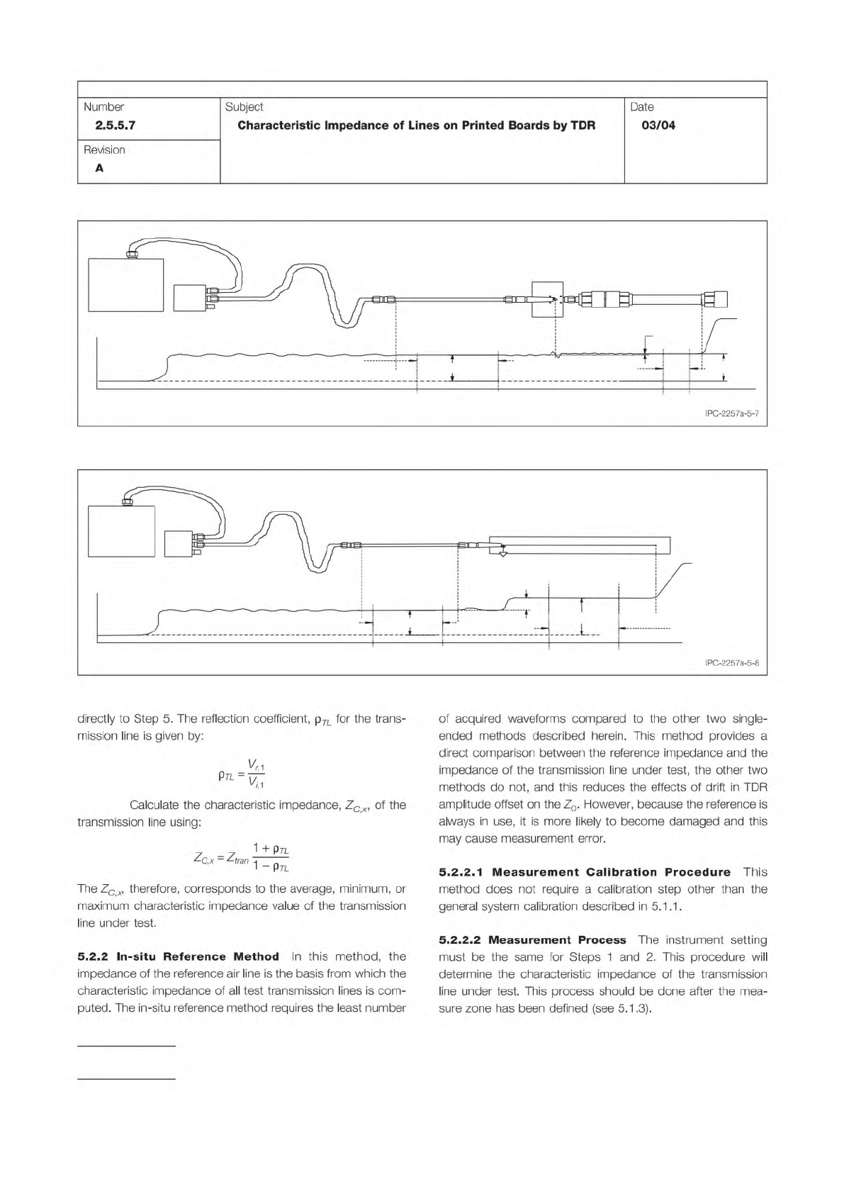
Figure 5-7 Calibration of Transfer Standard
TIME
TDR
INSTRUMENT
SPD
TRANSFER
STANDARD
V
tran,1
AIRLINE
V
std
V
r,0
PRECISION
RF CABLE
MEASUREMENT ZONE
for REFERENCE LINE
t
i,Ref
t
f,Ref
MEASUREMENT ZONE
for AIR LINE
t
f,std
t
i,std
Figure 5-8 TDR Measurement of Transmission Line Under Test
TDR
INSTRUMENT
SPD
TRANSFER
STANDARD
TIME
V
tran,3
V
C,ave
V
r,1
MEASUREMENT ZONE
for TRANSMISSION
LINE UNDER TEST
TRANSMISSION LINE UNDER TEST
PRECISION
RF CABLE
MEASUREMENT ZONE
for TRANSFER STANDARD
t
i,Ref
t
f,Ref
t
i,TL
t
f,TL
IPC-TM-650
Page 12 of 23
Number
2.5.5.7
Subject
Characteristic
Impedance
of
Lines
on
Printed
Boards
by
TDR
Date
03/04
Revision
A
IPC-2257a-5-8
directly
to
Step
5.
The
reflection
coefficient,
p
几
for
the
trans¬
mission
line
is
given
by:
c
%
PL%;
Calculate
the
characteristic
impedance,
ZCx,
of
the
transmission
line
using:
1
+
pn.
Zc,x
-
Ztran
:
j
~
~
1
—
Ptl
The
Ze*
therefore,
corresponds
to
the
average,
minimum,
or
maximum
characteristic
impedance
value
of
the
transmission
line
under
test.
5.2.2
In-situ
Reference
Method
In
this
method,
the
impedance
of
the
reference
air
line
is
the
basis
from
which
the
characteristic
impedance
of
all
test
transmission
lines
is
com¬
puted.
The
in-situ
reference
method
requires
the
least
number
of
acquired
waveforms
compared
to
the
other
two
single-
ended
methods
described
herein.
This
method
provides
a
direct
comparison
between
the
reference
impedance
and
the
impedance
of
the
transmission
line
under
test,
the
other
two
methods
do
not,
and
this
reduces
the
effects
of
drift
in
TDR
amplitude
offset
on
the
Zo.
However,
because
the
reference
is
always
in
use,
it
is
more
likely
to
become
damaged
and
this
may
cause
measurement
error.
5.2.2.
1
Measurement
Calibration
Procedure
This
method
does
not
require
a
calibration
step
other
than
the
general
system
calibration
described
in
5.1.1.
5.2.2.2
Measurement
Process
The
instrument
setting
must
be
the
same
for
Steps
1
and
2.
This
procedure
will
determine
the
characteristic
impedance
of
the
transmission
line
under
test.
This
process
should
be
done
after
the
mea¬
sure
zone
has
been
defined
(see
5.1.3).