IPC-TM-650 EN 2022 试验方法--.pdf - 第286页
Note 1: T a ble 1 Process S equence T e mp (°C) Time (Min) Conditioner 32 4 Rinse 16-27 2-3 Etch 66 6.5 Air Dry – 0.75 T riple R inse 16-27 3-5 Neutralizer 52 2.5 Rinse 25 5 Air Dry 25 Overnight T able 2 Modes of F ailur…
ASTM-E-345
The Institute for Interconnecting and Packaging Electronic Circuits
2215 Sanders Road • Northbrook, IL 60062-6135
Material in this Test Methods Manual was voluntarily established by Technical Committees of the IPC. This material is advisory only
and its use or adaptation is entirely voluntary. IPC disclaims all liability of any kind as to the use, application, or adaptation of this
material. Users are also wholly responsible for protecting themselves against all claims or liabilities for patent infringement.
Equipment referenced is for the convenience of the user and does not imply endorsement by the IPC.
Page 1 of 2
IPC-TM-650
TEST
METHODS
MANUAL
1
.0
Scope
To
determine
the
tensile
strength
(in
PSI)
and
the
elongation
(in
percentage)
of
copper
foil
at
ambient
and
elevated
temperatures
by
mechanical
force
testing.
2
.0
Applicable
Documents
Tensile
Strength
3
.0
Test
Specimens
Copper
foil
sufficient
in
size
to
permit
cutting
or
etching
of
five
specimens
10
inches
x
眩
inch.
Specimens
must
be
clean
cut
and
free
of
burrs
and
nicks.
4
.0
Apparatus
4.1
Constant
strain
rate
tensile
tester
capable
of
pulling
at
rate
of
0.050
and
2.0
inches/minute.
4.2
J
DC
#50
sample
cutter
inch
wide
x
10
inches
long.
4.3
A
shear
to
cut
10
inches
long
sample
to
6
inches
long.
4.4
Mettler
Balance
type
P120
or
equivalent.
4.5
Elevated
temperature
chamber
or
fixture,
attachable
to
the
tensile
tester,
capable
of
reaching
and
maintaining
a
tem¬
perature
of
180℃
±10℃
during
sample
testing.
5
.0
Procedure
5.1
Preparation
of
Samples
5.1.1
The
sample
should
be
smooth
and
undistorted
(wrinkle
free).
5.1.2
Use
the
JDC
#50
to
cut
five
tensile
specimens.
5.1.3
Cut
the
five
10
inches
long
specimens
to
6
inches
long.
Note:
Accuracy
is
important
in
the
N
inch
x
6
inches
dimen¬
sions
because
it
is
used
to
determine
foil
thickness
and
cross-
sectional
area.
Number
2.4.18
Subject
Tensile
Strength
and
Elongation,
Copper
Foil
Date
Revision
8/80
B
Originating
Task
Group
Printed
Board
Test
Methods
(7-1
1d)
5.2
Weighing
Samples
5.2.1
Weigh
tensile
sample
to
at
least
three
places
beyond
the
decimal
point,
in
grams.
5.2.2
Record
the
weight
and
calculate
the
mean
average
cross-sectional
area.
Note:
The
density
of
electrodeposited
copper
is
8.909
gm/cc
(16.389
cc/in3
x
8.909
gm/cc
=
146
gm/in3).
The
density
of
rolled
copper
is
8.93
gm/cc
(1
6.389
cc/in3
x
8.93
gm/cc
=
146.35
gm/in3).
Weight
of
tensile
sample
in
grams
Mean
average
thickness
=
Area
of
Tensile
The
density
sample
in
sq.
X
of
copper
in
inches
gm/in3
Weight
of
tensile
sample
in
grams
Mean
avg.
cross-sectional
area
=
Area
of
Tensile
The
density
sample
in
sq.
X
of
copper
in
inches
gm/in3
5.3
General
Test
Information
5.3.1
If
the
tensile
tester
is
equipped
with
an
area
compen¬
sator,
dial
the
mean
average
cross-sectional
area
into
it.
If
not
then
the
cross-sectional
area
has
to
be
used
to
compute
the
tensile
strength.
Note:
Tensile
Strength
Load
used
to
break
sample
in
lbs.
in
lbs/in2
-
Mean
average
cross-sectional
area
If
Tensile
Tester
is
equipped
with
area
compensator
after
the
test
is
complete,
the
Tensile
Strength
can
be
read
directly
from
the
chart.
5.3.2
Ambient
Temperature
Testing
5.3.2.1
Select
load
range.
5.3.2.2
Place
the
sample
in
the
jaws
of
the
Tensile
Tester
Note 1:
Table 1 Process Sequence
Temp (°C) Time (Min)
Conditioner 32 4
Rinse 16-27 2-3
Etch 66 6.5
Air Dry – 0.75
Triple Rinse 16-27 3-5
Neutralizer 52 2.5
Rinse 25 5
Air Dry 25 Overnight
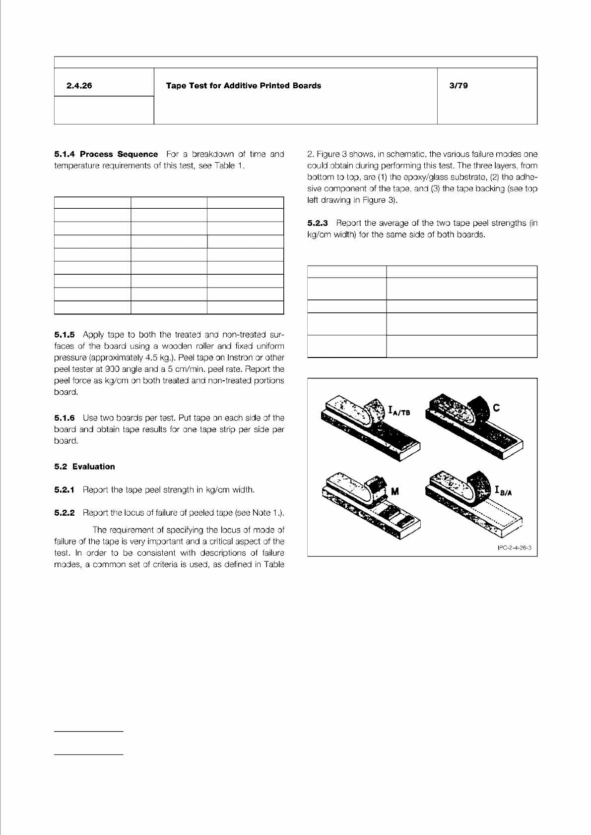
Table 2 Modes of Failure Shown in Figure 3
Notation
Meaning of Failure Mode
I
A/-TB
Interfacial failure, between adhesive
and tape backing
C Cohesive failure within tape adhesive
M Mixed failure mode, a combination of
the other types
I
B/A
Interfacial failure, between the board
and the adhesive of the tape.
Figure 3 Modes of Failure
IPC-TM-650
Number
Subject Date
Revision
Page 2 of 2
2.4.26
Tape
Test
for
Additive
Printed
Boards
3/79
5.1.4
Process
Sequence
For
a
breakdown
of
time
and
temperature
requirements
of
this
test,
see
Table
1
.
5.1.5
Apply
tape
to
both
the
treated
and
non-treated
sur¬
faces
of
the
board
using
a
wooden
roller
and
fixed
uniform
pressure
(approximately
4.5
kg.).
Peel
tape
on
Instron
or
other
peel
tester
at
900
angle
and
a
5
cm/min.
peel
rate.
Report
the
peel
force
as
kg/cm
on
both
treated
and
non-treated
portions
board.
5.1.6
Use
two
boards
per
test.
Put
tape
on
each
side
of
the
board
and
obtain
tape
results
for
one
tape
strip
per
side
per
board.
5.2
Evaluation
5.2.1
Report
the
tape
peel
strength
in
kg/cm
width.
5.2.2
Report
the
locus
of
failure
of
peeled
tape
(see
Note
1
.).
The
requirement
of
specifying
the
locus
of
mode
of
failure
of
the
tape
is
very
important
and
a
critical
aspect
of
the
test.
In
order
to
be
consistent
with
descriptions
of
failure
modes,
a
common
set
of
criteria
is
used,
as
defined
in
Table
2.
Figure
3
shows,
in
schematic,
the
various
failure
modes
one
could
obtain
during
performing
this
test.
The
three
layers,
from
bottom
to
top,
are
the
epoxy/glass
substrate,
(2)
the
adhe¬
sive
component
of
the
tape,
and
(3)
the
tape
backing
(see
top
left
drawing
in
Figure
3).
5.2.3
Report
the
average
of
the
two
tape
peel
strengths
(in
kg/cm
width)
for
the
same
side
of
both
boards.
ASTM E-345
IPC-TM-650
Material in this Test Methods Manual was voluntarily established by Technical Committees of IPC. This material is advisory only
and its use or adaptation is entirely voluntary. IPC disclaims all liability of any kind as to the use, application, or adaptation of this
material. Users are also wholly responsible for protecting themselves against all claims or liabilities for patent infringement.
Equipment referenced is for the convenience of the user and does not imply endorsement by IPC.
Page 1 of 3
Number
r
ASSOCIATION
CONNECTING
/
ELECTRONICS
INDUSTRIES
®
221
5
Sanders
Road
Northbrook,
IL
60062-6135
IPC-TM-650
TEST
METHODS
MANUAL
1
Scope
To
determine
the
tensile
strength
in
Mpa
(PSI)
and
the
elongation,
in
percentage,
of
electrodeposited
copper
plating
at
ambient
temperatures
by
mechanical
force
testing.
2
Applicable
Documents
Standard
Test
Methods
of
Tension
Testing
of
Metallic
Foil
IPC
Test
Methods
Manual
1
.7
Reporting,
Invalid
Test
Results
3
Test
Specimen
3.1
Plated
copper
samples
prepared
in
sheet
form
for
cut¬
ting
or
etching
into
the
appropriate
pattern,
or
pattern
plating
of
the
appropriate
form.
3.2
Samples
may
be
in
the
form
of
strips
of
13
mm
x
152
mm
[0.512
in
x
5.98
in]
or
in
the
form
of
“dogbone'
'
samples
as
described
in
ASTM
E-345,
Type
A.
The
thickness
of
the
samples
0.05
mm
to
0.1
mm
[0.001
97
in
to
0.00394
in].
Testing
shall
be
performed
on
ten
samples
(five
lengthwise
and
five
crosswise).
Specimens
must
be
wrinkle
free,
clean
cut,
and
free
of
burrs
and
nicks.
4
Apparatus
or
Material
4.1
Constant
strain
rate
tensile
tester
capable
of
pulling
at
rate
of
0.05
mm/mm
to
0.5
mm/mm
[0.00197
in/in
to
0.01
97
in/in]
per
minute
of
the
length
of
the
reduced
section
(or
the
distance
between
the
grips
for
straight
sided
speci¬
mens).
4.2
Sample
preparation
equipment
4.3
Sample
Size:
13
mm
wide
X
150
mm
[0.512
in
wide
x
5.91
in
long].
4.4
A
sample
cutter
capable
of
cutting
samples
to
the
appropriate
size
{see
6.1).
4.5
A
phototool
of
tensile
specimen
of
the
appropriate
size
(strip
or
dogbone).
2.4.18.1
Subject
Tensile
Strength
and
Elongation,
In-House
Plating
Date
Revision
05/04
A
Originating
Task
Group
Rigid
Printed
Board
Performance
Task
Group
(D-33a)
4.6
Stainless
steel
panel,
type
304
or
321
,
300
mm
X
300
mm
[11.8
in
x
11.8
in]
or
of
a
size
identical
to
that
used
to
produce
plated
product.
The
panel
surface
must
be
free
of
pits,
nicks,
and
scratches.
Low
carbon
stainless
steel
per¬
forms
best.
4.7
Weighing
balance
capable
of
resolving
to
1
mg.
4.8
Precision
linear
measuring
device
capable
of
measuring
to
the
nearest
0.025
mm
[0.000984
in].
4.9
Precision
micrometer
capable
of
measuring
to
the
near¬
est
0.0025
mm
[0.0000984
in].
4.10
An
oven
capable
of
maintaining
1
25
±
5
[257
°F
±9°F]-
5
Procedure
5.1
Samples
Preparation
Samples
may
be
prepared
using
the
phototool
Method
5.1.1
or
the
cut
Method
5.1
.2.
5.1.1
Phototool
Method
5.1
.1.1
Clean
the
stainless
steel
panel
using
a
standard
acid
or
alkali
cleaner
(preferably
reverse
current)
and
verify
by
per¬
forming
water-
break
test
to
insure
cleanliness.
5.1.
1.2
Apply
negative
resist
to
stainless
steel
plate.
5.1
.1.3
Image
plate
with
phototool
and
develop
image
using
any
acceptable
method.
5.1.
1.4
Inspect
image
for
integrity.
5.
1.1.5
Plate
the
imaged
panel
with
a
current
density
equivalent
to
production
current
density
to
a
thickness
of
0.05
mm
to
0.1
mm
[0.001
97
in
to
0.00394
in].
5.1.
1.6
Rinse
and
dry
plate.
5.1.
1.7
Remove
specimens
from
the
stainless
steel
by
lifting
a
corner
of
the
sample
with
a
knife
or
razor
exercising
care
not
to
bend
or
in
any
way
damage
the
sample.