IPC-TM-650 EN 2022 试验方法--.pdf - 第656页
METHOD B IPC-TM-650 Page 2 of 4 Number 2.6.3 Subject Moisture and Insulation Resistance, Printed Boards Date 05/04 Revision F 5.1.8 Specimen preparation for is now com¬ pleted, continue the procedure with 5.2. 5.1.9 METH…
IPC-CC-830
Material in this Test Methods Manual was voluntarily established by Technical Committees of IPC. This material is advisory only
and its use or adaptation is entirely voluntary. IPC disclaims all liability of any kind as to the use, application, or adaptation of this
material. Users are also wholly responsible for protecting themselves against all claims or liabilities for patent infringement.
Equipment referenced is for the convenience of the user and does not imply endorsement by IPC.
Page 1 of 4
r
ASSOCIATION
CONNECTING
/
ELECTRONICS
INDUSTRIES
®
221
5
Sanders
Road
Northbrook,
IL
60062-6135
IPC-TM-650
TEST
METHODS
MANUAL
1
Scope
This
test
method
is
to
determine
the
degradation
of
insulating
materials
by
examination
of
the
visual
and
electri¬
cal
insulation
resistance
properties
of
printed
board
speci¬
mens
after
exposure
to
high
humidity
and
heat
conditions.
This
method
allows
testing
with
(Method
A)
or
without
(Method
B)
Conformal
Coating.
When
not
specified,
Method
A
is
the
default
method.
2
Applicable
Documents
Qualification
and
Performance,
Insulating
Com¬
pounds
for
Printed
Circuits
Assemblies
3
Test
Specimens
3.1
Test
specimens
shall
be
comprised
of
a
minimum
of
two
conductor
lines
per
conductive
layer,
sufficient
to
allow
resis¬
tance
testing
between
adjacent
conductor
patterns
both
between
layers
and
on
the
same
layer.
See
6.1
for
examples
of
test
specimen
patterns
recommended
for
this
test
method.
4
Apparatus
or
Material
4.1
A
clean
test
chamber
capable
of
programming
and
recording
an
environment
of
temperature
ranging
between
25
±
2
[77
°F
±
4
°F)
and
65
±
2
[149
°F
±
4
°F],
and
85%
to
93%
relative
humidity.
4.2
A
power
supply
capable
of
producing
a
standing
bias
potential
of
100
volts
DC
with
a
tolerance
of
±
10%.
4.3
A
resistance
meter
capable
of
reading
high
resistance
at
the
voltage
described
in
the
procurement
documentation.
4.4
Solder
or
Flux-Cored
Solder
Flux
shall
be
removable
in
a
manner
which
will
not
adversely
affect
the
test
specimen.
4.5
Soft
Bristle
Brush.
4.6
Deionized
or
distilled
water
(2
megohm-cm,
minimum
resistivity
recommended).
4.7
Isopropyl
alcohol.
Number
2.6.3
Subject
Moisture
and
Insulation
Resistance,
Printed
Boards
Date
05/04
Revision
F
Originating
Task
Group
Rigid
Printed
Board
Performance
Task
Group
(D-33a)
4.8
Drying
oven(s)
capable
of
maintaining
50
±
5
[122
°F
±
9
°F]
and
125
±
5
[257
°F
±
9
°F].
4.9
Insulating
compound
(conformal
coating)
which
con¬
forms
to
IPC-CC-830.
4.10
Equipment
necessary
to
apply
and
cure
conformal
coating.
5
Procedure
5.1
Specimen
Preparation
5.1.1
Mark
specimen
with
positive,
permanent,
and
non¬
contaminating
identification.
5.1.2
Visually
inspect
the
test
specimens
for
any
obvious
defects,
as
described
in
the
applicable
performance
specifica¬
tion.
If
any
test
specimen
is
noncompliant,
the
test
specimen
should
be
replaced
and
the
replacement
noted.
5
J
.3
Solder
single
stranded
(to
decrease
the
opportunity
for
flux
contamination
from
the
wire)
insulated
wire
which
is
not
affected
by
the
test
environment
to
each
of
the
connection
points
of
the
test
specimens.
These
wires
will
be
used
to
con¬
nect
the
test
patterns
of
the
test
specimens
to
the
power
supply
and
for
insulation
resistance
testing.
5.1.4
Clean
test
lead
terminals
with
isopropyl
alcohol
and
scrub
with
a
soft
bristle
brush
for
a
minimum
of
30
seconds.
During
the
remainder
of
the
test
specimen
preparation,
handle
test
specimens
by
the
edges
only
(see
6.2).
5.1.5
Spray
rinse
thoroughly
with
fresh
isopropyl
alcohol.
Hold
test
specimen
at
an
approximate
30°
angle
and
spray
from
top
to
bottom.
5.1.6
Rinse
cleaned
area
thoroughly
with
fresh
deionized
or
distilled
water.
Hold
test
specimen
at
an
approximate
30°
angle
and
spray
from
top
to
bottom.
5.1.7
Dry
test
specimens
in
a
drying
oven
for
a
minimum
of
three
hours
at
an
oven
temperature
of
between
50
±
5
[122
°F
±
9
°F)
(see
6.3).
METHOD B
IPC-TM-650
Page 2 of 4
Number
2.6.3
Subject
Moisture
and
Insulation
Resistance,
Printed
Boards
Date
05/04
Revision
F
5.1.8
Specimen
preparation
for
is
now
com¬
pleted,
continue
the
procedure
with
5.2.
5.1.9
METHOD
A
-
Application
of
Conformal
Coating.
Continuation
of
Sample
Preparation
Apply
coating
to
the
appropriate
area
of
the
test
specimen,
in
a
manner
concurrent
with
user's
production
techniques
or
as
specified
by
the
coat¬
ing
supplier.
5.1.10
After
the
application
of
coating,
the
test
specimens
are
to
be
cured,
as
specified
by
the
coating
supplier.
5.1.11
After
curing,
stabilize
to
ambient
temperature.
5.2
Test
5.2.1
Take
the
initial
insulation
resistance
measurements
at
laboratory
ambient
temperature.
Apply
the
voltage
specified
in
the
procurement
documentation
on
the
test
specimen's
test
points
as
specified
in
5.2.2
with
the
resistance
meter,
and
take
the
reading
after
measurement
stabilization.
5.2.2
Test
points
on
the
test
specimens
shall
be
connected
in
a
manner
that
will
allow
adjacent
conductor
patterns,
both
between
conductor
layers
and
on
the
same
conductor
layer,
to
alternate
between
the
positive
(+)
and
negative
(-)
terminals
of
the
power
supply
or
resistance
meter.
5.2.3
Place
test
specimens
in
chamber
in
a
vertical
position
and
under
a
condensation
drip
shield.
Connect
the
DC
volt¬
age
source
to
the
test
specimen
test
points
as
indicated
in
5.2.2.
Apply
a
1
00
±
1
0
volts
DC
polarization
voltage
to
all
test
specimens.
5.2.4
Expose
test
specimens
to
one
of
the
following
speci¬
fied
test
conditions:
(See
6.4.)
(a)
Class
1
-
35
±
5
[95
°F
±
9
°F],
85%
to
93%
rela¬
tive
humidity,
for
four
days
(static).
(b)
Class
2-50
℃
±5℃
[122
°F
±
9
°F],
85%
to
93%
rela¬
tive
humidity,
for
seven
days
(static).
(c)
Class
3-20
cycles
of
temperature
ranging
from
25
+5/-2
[77
°F
+9/-4
°F]
to
65
℃
±2℃[149
°F
±
4
°F],
85%
to
93%
relative
humidity,
1
60
hours
total.
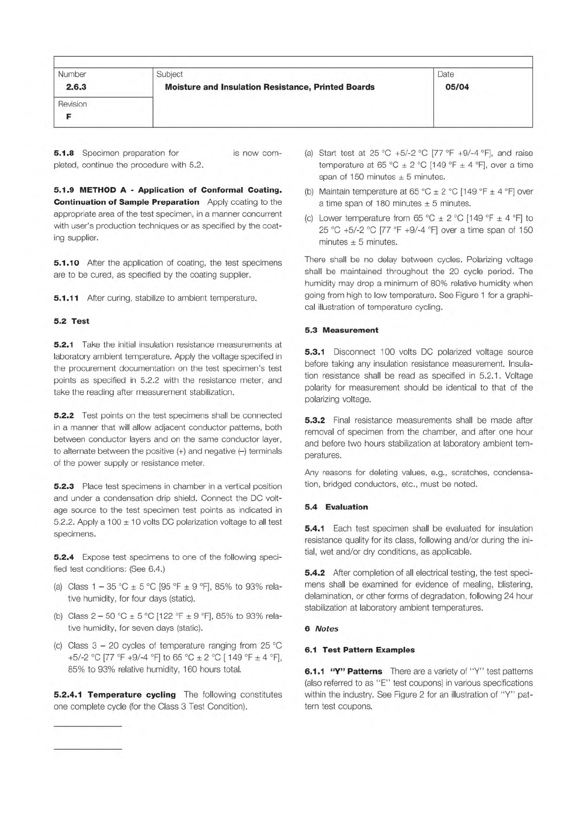
5.2.4.1
Temperature
cycling
The
following
constitutes
one
complete
cycle
(for
the
Class
3
Test
Condition).
(a)
Start
test
at
25
+5/-2
[77
°F
+9/-4
°F],
and
raise
temperature
at
65
±
2
[149
°F
±
4
°F],
over
a
time
span
of
1
50
minutes
±
5
minutes.
(b)
Maintain
temperature
at
65
±
2
[149
°F
±
4
°F]
over
a
time
span
of
1
80
minutes
土
5
minutes.
(c)
Lower
temperature
from
65
±
2
[149
°F
±
4
°F]
to
25
+5/-2
[77
°F
+9/-4
°F]
over
a
time
span
of
1
50
minutes
±
5
minutes.
There
shall
be
no
delay
between
cycles.
Polarizing
voltage
shall
be
maintained
throughout
the
20
cycle
period.
The
humidity
may
drop
a
minimum
of
80%
relative
humidity
when
going
from
high
to
low
temperature.
See
Figure
1
for
a
graphi¬
cal
illustration
of
temperature
cycling.
5.3
Measurement
5.3.1
Disconnect
100
volts
DC
polarized
voltage
source
before
taking
any
insulation
resistance
measurement.
Insula¬
tion
resistance
shall
be
read
as
specified
in
5.2.1
.
Voltage
polarity
for
measurement
should
be
identical
to
that
of
the
polarizing
voltage.
5.3.2
Final
resistance
measurements
shall
be
made
after
removal
of
specimen
from
the
chamber,
and
after
one
hour
and
before
two
hours
stabilization
at
laboratory
ambient
tem¬
peratures.
Any
reasons
for
deleting
values,
e.g.,
scratches,
condensa¬
tion,
bridged
conductors,
etc.,
must
be
noted.
5.4
Evaluation
5.4.1
Each
test
specimen
shall
be
evaluated
for
insulation
resistance
quality
for
its
class,
following
and/or
during
the
ini¬
tial,
wet
and/or
dry
conditions,
as
applicable.
5.4.2
After
completion
of
all
electrical
testing,
the
test
speci¬
mens
shall
be
examined
for
evidence
of
mealing,
blistering,
delamination,
or
other
forms
of
degradation,
following
24
hour
stabilization
at
laboratory
ambient
temperatures.
6
Notes
6.1
Test
Pattern
Examples
6.1.1
“Y”
Patterns
There
are
a
variety
of
"Y”
test
patterns
(also
referred
to
as
"E"
test
coupons)
in
various
specifications
within
the
industry.
See
Figure
2
for
an
illustration
of
“Y”
pat¬
tern
test
coupons.
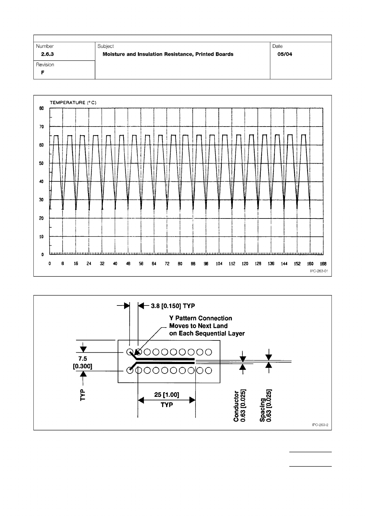
Figure 1 Moisture and Insulation Resistance Test Graph
Figure 2 Insulation Resistance Coupon E (See Table 7-3), mm [in]
IPC-TM-650
Page 3 of 4
Number
2.6.3
Subject
Moisture
and
Insulation
Resistance,
Printed
Boards
Date
05/04
Revision
F
TEMPERATURE
(
℃)
8.0
Jolonpuoo
IPC-263-2