IPC-TM-650 EN 2022 试验方法--.pdf - 第254页
IPC-TM-650 T est M ethods Manual The Institute for Int erconnecting and Packaging E lectronic Circuits 2215 S anders Road • Northbrook, IL 60062-6135 Material in this T est M ethods Manual was voluntarily establis hed by…

/
Figure 3 Chain to Hemostat Adapter
IPC-TM-650
Number
Subject Date
Revision
Page 3 of 3
2.4.8.1
Peel
Strength,
Metal
Foil
(Keyhole
Method
For
Thin
Laminates)
1/86
5.4
Evaluation
5.4.1
Calculate
the
peel
strength
per
mm
of
width
by
mea¬
suring
the
strip
width
in
mm,
using
the
following
formula:
1
mm
—
—
x
observed
pull
force
=
measured
strip
width
in
mm
peel
strength
mm
width
6
Notes
6.1
Peel
strength
is
usually
the
minimum
peel
strength
observed.
IPC-TM-650 Test Methods Manual
The Institute for Interconnecting and Packaging Electronic Circuits
2215 Sanders Road • Northbrook, IL 60062-6135
Material in this Test Methods Manual was voluntarily established by Technical Committees of the IPC. This material is advisory only
and its use or adaptation is entirely voluntary. IPC disclaims all liability of any kind as to the use, application, or adaptation of this
material. Users are also wholly responsible for protecting themselves against all claims or liabilities for patent infringement.
Equipment referenced is for the convenience of the user and does not imply endorsement by the IPC.
Page 1 of 3
IPC-TM-650
TEST
METHODS
MANUAL
1
.0
Scope
The
purpose
of
this
test
is
to
determine
the
peel
strength
of
metal
cladding
to
the
base
laminate
while
at
elevated
temperature;
and
to
evaluate
the
base
laminate
material
after
the
peel
strength
test
is
completed
for
degrada¬
tion
due
to
the
conditioning.
2
.0
Applicable
Documents
Method
2.4.8.
1
,
Peel
Strength,
Metal
Foil
(Keyhole
Method
for
Thin
Laminates)
Method
5.8.3,
Peel
Strength
Test
Pattern
3
.0
Test
Specimens
3.1
Size
and
Configuration
Specimens
shall
be
50.8
mm
x
50.8
mm
[2.0
x
2.0
in]
by
the
thickness
of
the
laminate.
Cladding
test
strips
shall
be
as
specified
(see
5.1
.2).
3.2
Quantity
and
Sampling
Unless
otherwise
specified,
specimens
shall
be
one
lengthwise
for
each
clad
side
and
one
crosswise
for
each
clad
side.
The
outside
25.4
mm
[1
in]
bor¬
der
of
the
parent
sheet
or
panel
shall
be
excluded.
4
.0
Apparatus
or
Material
4.1
Tensile
Tester
A
tensile
strength
tester
equipped
with
a
load
cell,
capable
of
measuring
to
the
nearest
0.0045
kg
[0.01
lbs.]
and
a
light
load
wire
or
chain
and
clamp
at
least
457
mm
[18
in]
long
(its
weight
is
included
in
the
load
cell
cal¬
culation).
The
clamp
jaws
must
cover
the
entire
width
of
each
peel
strip
tab.
Any
equipment
or
apparatus
having
the
described
accuracy,
precision,
and
reproducibility
may
be
used.
4.2
Hot
Fluid
Bath
A
fluid
bath
or
pot
capable
of
maintain¬
ing
the
specified
fluid
at
the
specified
temperature
when
mea¬
sured
2.54
mm
[1
.0
in]
below
the
surface.
4.2.1
Dow
Silicone
Fluid
No.
704,
or
equivalent.
4.3
Specimen
Hold-down
A
suitable
hold-down
clamping
system
equivalent
in
performance
as
that
defined
in
IPC-TM-
650,
Method
2.4.
8.1.
Number
2.4.8.2
Subject
Peel
Strength
of
Metallic
Clad
Laminates
at
Elevated
Temperature
(Hot
Fluid
Method)
Date
Revision
12/94
A
Originating
Task
Group
MIL-P-13949
Test
Methods
Task
Group
(7-1
1b)
4.4
Data
Collection
For
qualification
testing,
a
recording
system
capable
of
permanent
data
retention
incorporated
into
the
test
apparatus.
4.5
Measuring
device
capable
of
measuring
from
0.000
to
12.7
mm
[0.500
in]
to
within
±
0.0025
mm
[0.0001
in].
4.6
Etch
Resist
Materials
or
Systems
4.6.1
Plater's
tape,
or
equivalent,
to
act
as
etch
resist
for
strip
formation
of
the
specified
widths
(see
3.3
and
3.4).
4.6.2
Photoresist
system
(printing,
developing,
and
strip¬
ping).
4.7
Etching
system
capable
of
complete
removal
of
metallic
cladding.
4.8
Circulating
air
oven
capable
of
maintaining
125
土
2
℃
[257
±
3.6°F].
5
.0
Procedure
5.1
Specimen
Preparation
5.1.1
Cut
the
specimens
from
the
laminate
sample.
Speci¬
mens
shall
be
taken
no
closer
than
2.54
mm
[1
.0
in]
from
the
edge
of
the
laminate
sheet
as
manufactured.
5.1.2
Specimens
shall
be
prepared
with
at
least
four
resist
strips
of
3.18
mm
[0.125
in]
width
and
then
etched,
cleaned
and
processed
using
standard
industry
practices
and
equip¬
ment.
For
qualification
and
referee
testing
the
specimen
shall
be
photoimaged
in
accordance
with
the
artwork
shown
in
Method
5.8.3
of
IPC-TM-650
and
reproduced
here
as
Figure
1
,
except
that
tab
ends
are
optional.
Specimens
shall
be
etched
so
that
the
conductor
strips
on
one
specimen
are
in
one
direction
per
Figure
1
.
Double
clad
laminate
shall
have
each
side
tested
using
separate
specimens.
The
opposite
side
cladding
shall
be
either
fully
removed
or
left
fully
clad.
Separate
specimens
for
both
the
warp
and
fill
directions
are
required
for
each
side.
For
referee
testing
the
cladding
on
the
opposite
side
shall
remain.
/
IPC-I-002102
Figure 1 Multiple Failure Modes
Peel Distance
Load
High Peel Strength
Failure Mode
Low Peel Strength
Failure Mode
IPC-TM-650
Number
Subject Date
Revision
Page 2 of 3
2.4.8.2
Peel
Strength
of
Metallic
Clad
Laminates
at
Elevated
Temperature
(Hot
Fluid
Method)
12/94
A
5.1.3
Thin
specimens
may
be
provided
with
support
by
bonding
them
to
a
rigid
substrate
base,
or
may
be
tested
with
the
aid
of
the
keyhole
fixture
(see
Figure
2).
For
referee
testing
of
laminates
less
than
0.51
mm
[0.020
in],
the
specimens
shall
be
bonded
to
a
rigid
substrate
or
laminate.
Note:
Peel
values
can
be
affected
by
the
adhesive
used
to
bond
the
specimen
to
the
rigid
substrate.
It
is
imperative
that
the
best
adhesive
be
found
for
the
type
of
materials
being
bonded
to
least
influence
the
true
peel
strength
value.
5.1.4
Peel
the
test
strip
back
no
more
than
12.7
mm
[0.5
in]
at
the
tab
end.
5.1.5
For
qualification
or
referee
testing
purposes,
speci¬
mens
shall
be
preconditioned
by
baking
at
125
土
2
℃
[257
土
3.6°F]
for
a
minimum
of
two
hours.
This
preconditioning
is
in
addition
to
elevated
test
temperature
requirements
on
the
appropriate
material
specification.
5.1.6
Heat
fluid
bath
to
specified
temperature
and
stabilize
at
least
5
minutes.
Measure
temperature
approximately
25.4
mm
[1
.0
in]
below
surface.
5.2
Measurement
5.2.1
Peel
Strength
Determination
5.2.1
.1
Clamp
the
tab
end
(if
present)
of
each
individual
test
strip
and
place
specimen
and
clamp
into
fluid
bath
immersing
specimen
horizontally
approximately
25.4
mm
[1
.0
in]
below
the
surface.
5.2.1.
2
Fasten
specimen
with
hold
down
fixture
so
that
an
unencumbered
vertical
pull
can
be
exerted.
The
end
of
the
test
strip
and
the
wire
connecting
the
clamp
to
the
tensile
tester
must
be
free
to
pull
vertically
within
5°.
5.2.1.
3
Prior
to
starting
test,
allow
immersed
specimen
to
stabilize
at
the
specified
temperature
for
laminates
to
0.51
mm
[0.020
in]
or
for
laminates
greater
than
0.51
mm
[0.20
in].
5.2.1.
4
Start
test
and
apply
force
in
the
vertical
direction
at
the
rate
of
50.8
mm
[2.0
in]
per
minute,
until
at
least
25.4
mm
[1
.0
in]
of
the
test
strip
has
been
pulled,
or
the
strip
breaks
or
tears.
(See
6.1).
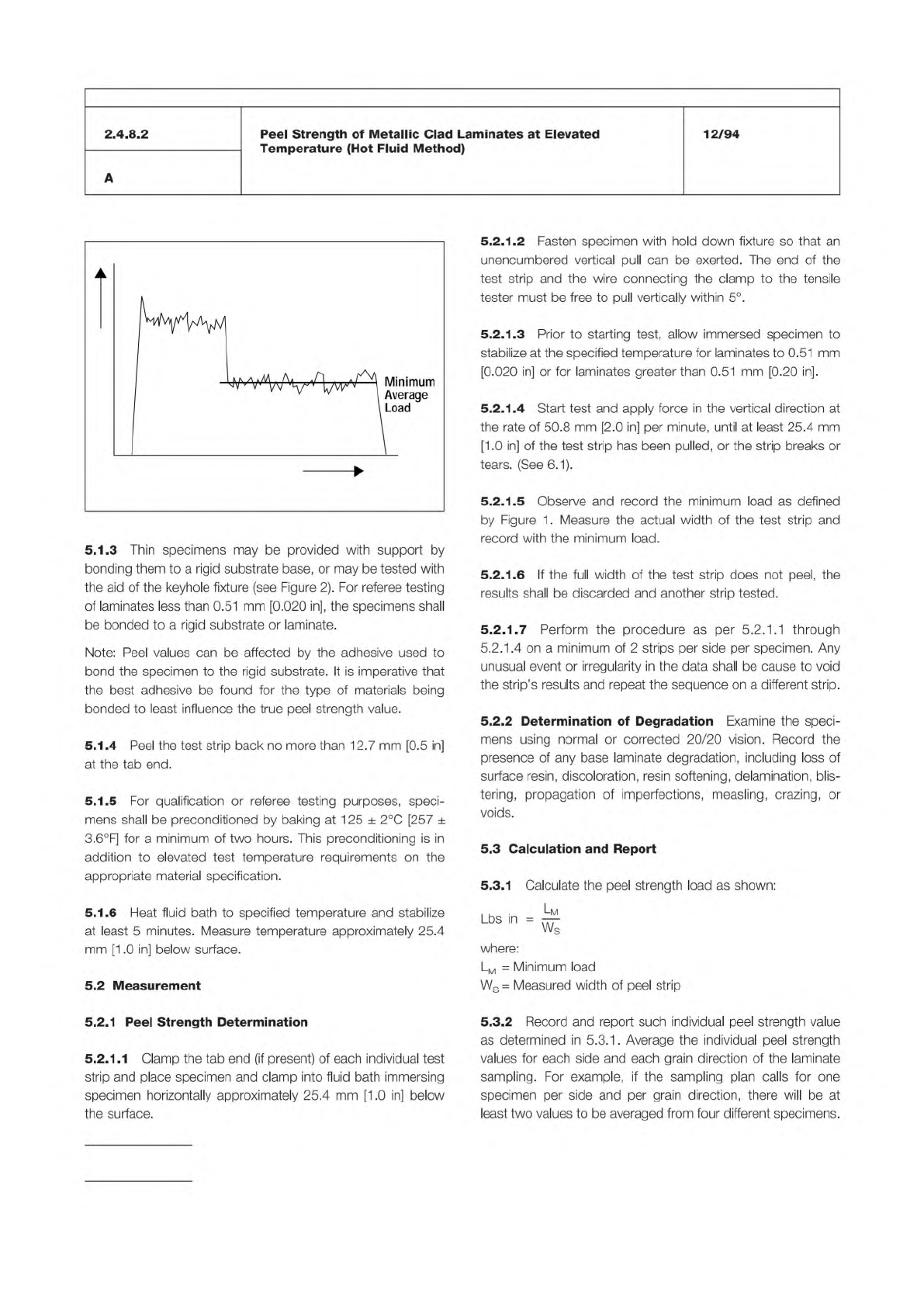
5.2.1.
5
Observe
and
record
the
minimum
load
as
defined
by
Figure
1
.
Measure
the
actual
width
of
the
test
strip
and
record
with
the
minimum
load.
5.2.1.
6
If
the
full
width
of
the
test
strip
does
not
peel,
the
results
shall
be
discarded
and
another
strip
tested.
5.2.
1.7
Perform
the
procedure
as
per
5.2.1
.1
through
5.2.1
.4
on
a
minimum
of
2
strips
per
side
per
specimen.
Any
unusual
event
or
irregularity
in
the
data
shall
be
cause
to
void
the
strip's
results
and
repeat
the
sequence
on
a
different
strip.
5.2.2
Determination
of
Degradation
Examine
the
speci¬
mens
using
normal
or
corrected
20/20
vision.
Record
the
presence
of
any
base
laminate
degradation,
including
loss
of
surface
resin,
discoloration,
resin
softening,
delamination,
blis¬
tering,
propagation
of
imperfections,
measling,
crazing,
or
voids.
5.3
Calculation
and
Report
5.3.1
Calculate
the
peel
strength
load
as
shown:
. .
.
Lm
出
m
=
砾
where:
Lm
=
Minimum
load
Ws=
Measured
width
of
peel
strip
5.3.2
Record
and
report
such
individual
peel
strength
value
as
determined
in
5.3.1
.
Average
the
individual
peel
strength
values
for
each
side
and
each
grain
direction
of
the
laminate
sampling.
For
example,
if
the
sampling
plan
calls
for
one
specimen
per
side
and
per
grain
direction,
there
will
be
at
least
two
values
to
be
averaged
from
four
different
specimens.