IPC-TM-650 EN 2022 试验方法--.pdf - 第77页
ASTM E1 1 BS.410 DIN 4188 ISO 565 ISO 3310 T a ble 1 Screen Openin g T ype 1 150 75 20 T ype 2 75 4 5 20 T ype 3 45 25 20 T ype 4 38 20 The Institute for Int erconnecting and Packaging E lectronic Circuits 2215 Sanders R…
IPC-TM-650
Number
Subject Date
Revision
Page 2 of 2
2.2.4
Dimensional
Stability,
Flexible
Dielectric
Materials
5/98
C
Twenty-four
hour
stabilization
is
referee
method.
5.2
Method
A
Dimensional
stability
of
unclad
material
due
to
thermal
exposure
—
standard
condition.
(1)
Place
test
specimen
unconstrained
in
an
oven
maintained
at
150℃
±
2
℃
for
30
±
2
minutes.
(2)
Cool
specimen
to
standard
conditions
of
23℃
±
2
℃
and
50%
±
5%
RH
for
24
hours
minimum
(see
5).
(3)
Remeasure
separation
of
holes/lines
and
record
as
final
measurement
after
thermal
exposure
(F).
5.3
Method
B
Dimensional
stability
of
metal
clad
dielectrics
due
to
metal
removal.
(1)
Chemically
erode
the
metal
away
except
for
the
target
areas,
which
can
have
up
to
13
mm
x
13
mm
square
metal,
using
an
etchant
that
has
no
detrimental
effect
on
either
the
dielectric
or
adhesive.
Wash
and
dry.
The
test
specimen
should
be
unconstrained
during
the
etching,
washing,
and
drying
operation.
(2)
Stabilize
test
specimen
for
24
hours
at
23℃
±
2
℃
and
50%
±
5%
RH
(see
5.1).
(3)
Remeasure
separation
of
holes/lines
and
record
as
final
measurement
after
etching
(F2).
5.4
Method
C
Dimensional
stability
of
dielectric
due
to
thermal
exposure
and
metal
removal,
using
specimens
from
Method
B.
Place
unconstrained
etched,
conditioned,
and
measured
specimen
from
Method
B
in
an
oven
maintained
at
150℃
土
2
℃
for
30
±
2
minutes.
(2)
Stabilize
specimen
at
23℃
±
2
℃
and
50%
±
5%
RH
for
24
hours
and
remeasure
separation
of
holes
(see
5.1).
(3)
Remeasure
separation
of
holes/lines
and
record
as
final
after
etching
and
thermal
exposure
(F3).
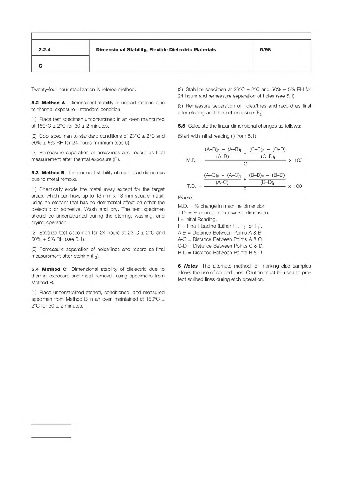
5.5
Calculate
the
linear
dimensional
changes
as
follows:
(Start
with
initial
reading
(I)
from
5.1)
(A—B)f
-
(A-B)|
(O-D)F
-
(C-D)|
,八
c、
+
e
c、
(A-C)f
-
(
A-C)|
(B-D)f
-
(
B-D)|
(A-C)|
*
(B-D)!
I
.U.
—
2
Where:
M.D.
=
%
change
in
machine
dimension.
T.D.
=
%
change
in
transverse
dimension.
I
=
Initial
Reading.
F
二
Final
Reading
(Either
F1
,
F2,
or
F3).
A-B
=
Distance
Between
Points
A
&
B.
A-C
=
Distance
Between
Points
A
&
C.
C-D
=
Distance
Between
Points
C
&
D.
B-D
=
Distance
Between
Points
B
&
D.
6
Notes
The
alternate
method
for
marking
clad
samples
allows
the
use
of
scribed
lines.
Caution
must
be
used
to
pro¬
tect
scribed
lines
during
etch
operation.
x
100
x
100
ASTM E11
BS.410
DIN 4188
ISO 565
ISO 3310
Table 1 Screen Opening
Type 1 150 75 20
Type 2 75 45 20
Type 3 45 25 20
Type 4 38 20
The Institute for Interconnecting and Packaging Electronic Circuits
2215 Sanders Road • Northbrook, IL 60062
Material in this Test Methods Manual was voluntarily established by Technical Committees of the IPC. This material is advisory only
and its use or adaptation is entirely voluntary. IPC disclaims all liability of any kind as to the use, application, or adaptation of this
material. Users are also wholly responsible for protecting themselves against all claims or liabilities for patent infringement.
Equipment referenced is for the convenience of the user and does not imply endorsement by the IPC.
Page 1 of 2
IPC-TM-650
TEST
METHODS
MANUAL
1
.0
Scope
A
method
for
determining
whether
or
not
the
powder
in
a
solder
paste
complies
with
the
relevant
powder
type.
The
ASTM
B-214
standard
screen
powder
size
distribu¬
tion
method
has
been
found
to
be
acceptable.
2
.0
Applicable
Documents
3
.0
Test
Specimen
Approximately
1
50
grams
of
solder
paste
4
.0
Equipment/Apparatus
Vibratory
test
sieving
machine
Test
sieves
to
BS.410,
ASTM
El
1
,
DIN
4188,
or
ISO
565
and
ISO
3310
with
mesh
openings
of
150,
75,
45,
38,
25
and
20
micrometers
Sieve
bottom
receiver
and
lid
Balance
(scale)
with
an
accuracy
of
0.01
g
Beaker
400-600
ml
Watch
glass
Solvent
Acetone
Spatula
5
.0
Procedure
5.1
Preparation
5.1.1
Wait,
if
necessary,
until
the
solder
paste
is
at
room
temperature.
5.2
Test
Number
2.2.14
Subject
Solder
Powder
Particle
Size
Distribution
—
Screen
Method
for
Types
1-4
Date
Revision
1/95
Originating
Task
Group
Solder
Paste
Task
Group
(5-24b)
5.2.2
Weigh
paste
containing
approximately
11
0
g
of
solder
alloy
into
the
carefully
cleaned
beaker.
5.2.3
Add
approximately
50
ml
solvent.
5.2.4
Stir
the
mixture
with
the
spatula
so
that
the
flux
in
the
paste
can
dissolve
in
the
solvent.
5.2.5
Cover
the
beaker
with
the
watch
glass.
5.2.6
Let
the
beaker
with
the
watch
glass
stand
until
the
solder
powder
settles.
5.2.7
Decant,
carefully,
as
much
as
possible
of
the
fluid
without
losing
any
of
the
solder
powder.
5.2.8
Repeat
the
extraction
procedure
five
times,
using
50
ml
solvent
for
each
extraction.
5.2.9
Add
approximately
50
ml
acetone
to
the
washed
sol¬
der
powder
and
stir
with
the
spatula
to
assist
in
drying.
5.2.10
Let
the
solder
powder
settle.
5.2.1
1
Decant,
carefully,
as
much
as
possible
of
the
acetone.
5.2.12
Repeat
the
acetone
wash
2
additional
times.
5.2.13
Allow
the
powder
to
dry
at
ambient
temperature
until
the
weight
is
constant.
5.2.14
Weigh
test
sieves,
with
mesh
opening
sizes
appro¬
priate
for
the
type
of
powder
being
tested,
and
the
sieve
bot¬
tom
receiver.
Typical
sieves
required
are
shown
in
Table
1
.
5.2.1
Homogenize
the
paste
by
stirring
with
the
spatula.
Table 2A % of Sample by Weight—Nominal Sizes
Less Than 1%
Larger Than
80% Minimum
Between
10% Maximum
Less Than
Type 1 150 Microns 150–75 Microns 20 Microns
Type 2 75 Microns 75–45 Microns 20 Microns
Type 3 45 Microns 45–25 Microns 20 Microns
Table 2B % of Sample by Weight—Nominal Sizes
Less Than 1%
Larger Than
90% Minimum
Between
10% Maximum
Less Than
Type 4 38 Microns 38−20 Microns 20 Microns
Table 3
Type 1 +150µm +75 µm +20 µm –20 µm
Type 2 + 75 µm +45 µm +20 µm –20 µm
Type 3 + 45 µm +25 µm +20 µm –20 µm
Type 4 + 38 µm +20 µm –20 µm
IPC-TM-650
Number
Subject Date
Revision
Page 2 of 2
2.2.14
Solder
Powder
Particle
Size
Distribution
—
Screen
Method
for
Types
1-4
1/95
5.2.15
Place
the
sieves
on
the
receiver
with
the
sieve
with
the
smallest
opening
on
the
receiver
and
processing
sequen¬
tially
upward
to
the
largest
opening
screen.
5.2.16
Weigh
the
powder
and
put
this
in
the
top
sieve.
5.2.17
Place
the
lid
on
the
sieve
combination
and
transfer
this
to
the
sieving
machine.
5.2.18
Run
the
machine
for
approximately
40
minutes.
5.2.19
Reweigh
the
sieves
and
the
receiver.
5.2.20
Subtract
the
original
weights
of
the
sieves
and
the
receiver
to
obtain
the
weights
of
powder
with
sizes
greater
than,
within,
and
less
than
the
nominal
size
range
from
Table
2A
and
2B.
5.3
Evaluation
Express
the
masses
of
the
powder
above,
within,
and
below
the
nominal
size
range
as
percentages
of
the
mass
of
the
original
sample.
Enter
data
in
Table
3.