IPC-TM-650 EN 2022 试验方法--.pdf - 第542页
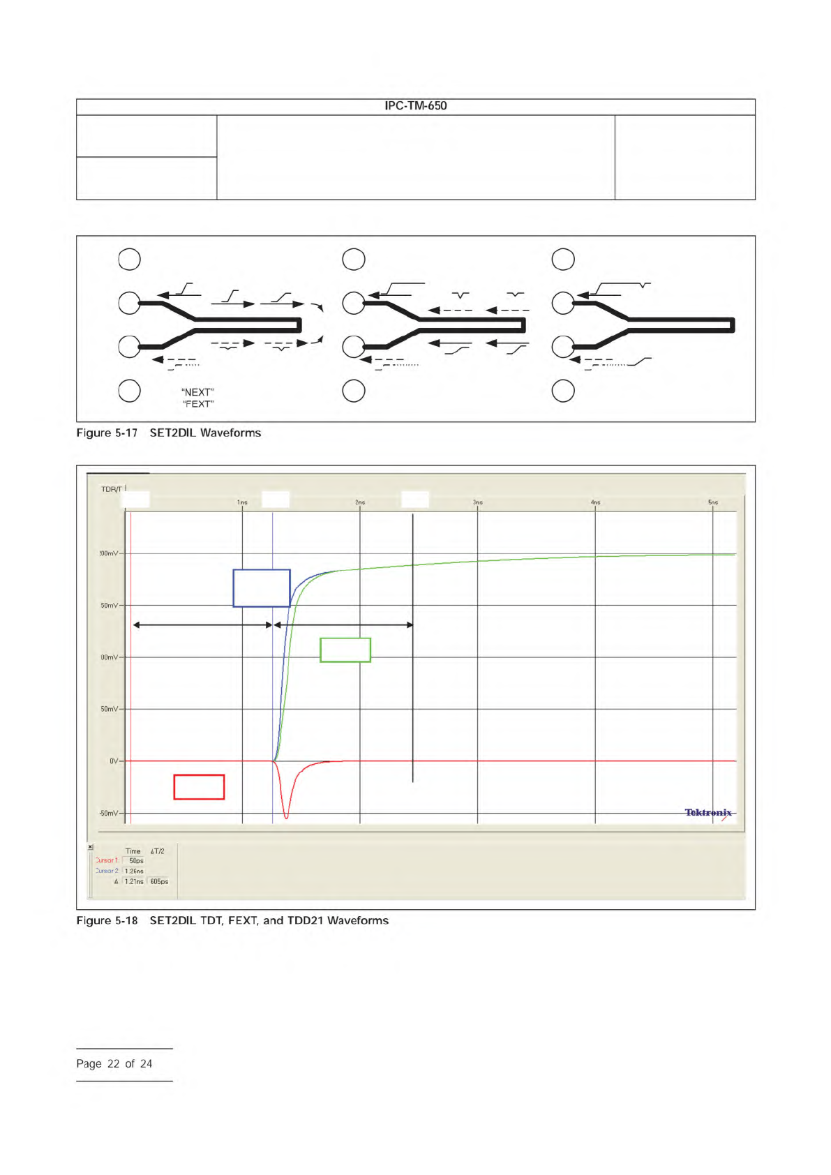
IPC-25512-5-17 G + G q1 q2 G + G G + G TDR TDT NEXT FEXT TDT FEXT FEXT FEXT TDT TDT NEXT TDR NEXT + TDT TDR + FEXT Note: = Near End Cross Talk = Far End Cross Talk q1 final q2 final SET2DIL TDD21 Td Td t0 t1 t2 Number 2.…
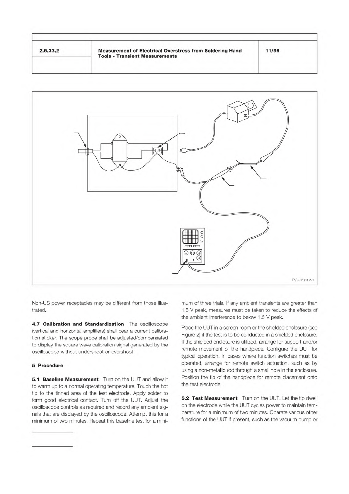
Figure 1 Apparatus for Transient Measurement
OSCILLOSCOPE
AC LINE
FILTER ASSEMBLY
1 MEGOHM
INPUT
RECEPTACLE
FOR UUT
UUT
10 MEGOHM
(X10) SCOPE
PROBE
TEST
ELECTRODE
STRAIN
RELIEF
TO
AC
AC
LINE
FILTER
METAL BOX
BLK BLK
WHTWHT
GRN GRN
G
R
N
IPC-TM-650
Number
Subject Date
Revision
Page 2 of 4
2.5.33.2
Measurement
of
Electrical
Overstress
from
Soldering
Hand
Tools
-
Transient
Measurements
11/98
IPC-2.5.33.2-1
Non-US
power
receptacles
may
be
different
from
those
illus¬
trated.
4.7
Calibration
and
Standardization
The
oscilloscope
(vertical
and
horizontal
amplifiers)
shall
bear
a
current
calibra¬
tion
sticker.
The
scope
probe
shall
be
adjusted/compensated
to
display
the
square
wave
calibration
signal
generated
by
the
oscilloscope
without
undershoot
or
overshoot.
5
Procedure
5.1
Baseline
Measurement
Turn
on
the
UUT
and
allow
it
to
warm
up
to
a
normal
operating
temperature.
Touch
the
hot
tip
to
the
tinned
area
of
the
test
electrode.
Apply
solder
to
form
good
electrical
contact.
Turn
off
the
UUT.
Adjust
the
oscilloscope
controls
as
required
and
record
any
ambient
sig¬
nals
that
are
displayed
by
the
oscilloscope.
Attempt
this
for
a
minimum
of
two
minutes.
Repeat
this
baseline
test
for
a
mini¬
mum
of
three
trials.
If
any
ambient
transients
are
greater
than
1.5
V
peak,
measures
must
be
taken
to
reduce
the
effects
of
the
ambient
interference
to
below
1.5
V
peak.
Place
the
UUT
in
a
screen
room
or
the
shielded
enclosure
(see
Figure
2)
if
the
test
is
to
be
conducted
in
a
shielded
enclosure.
If
the
shielded
enclosure
is
utilized,
arrange
for
support
and/or
remote
movement
of
the
handpiece.
Configure
the
UUT
for
typical
operation.
In
cases
where
function
switches
must
be
operated,
arrange
for
remote
switch
actuation,
such
as
by
using
a
non-metallic
rod
through
a
small
hole
in
the
enclosure.
Position
the
tip
of
the
handpiece
for
remote
placement
onto
the
test
electrode.
5.2
Test
Measurement
Turn
on
the
UUT.
Let
the
tip
dwell
on
the
electrode
while
the
UUT
cycles
power
to
maintain
tem¬
perature
for
a
minimum
of
two
minutes.
Operate
various
other
functions
of
the
UUT
if
present,
such
as
the
vacuum
pump
or
IPC-25512-5-17
G
+
G
q1
q2
G
+
G
G
+
G
TDR
TDT
NEXT
FEXT
TDT
FEXT
FEXT
FEXT
TDT
TDT
NEXT
TDR
NEXT + TDT
TDR + FEXT
Note:
= Near End Cross Talk
= Far End Cross Talk
q1 final
q2 final
SET2DIL
TDD21
Td Td
t0 t1 t2
Number
2.5.5.12
Subject
Test Methods to Determine the Amount of Signal Loss on
Printed Boards
Date
07/12
Revision
A
IPC-TM-650
—
Page
22
of
24
5.5 FD Procedure
This specification currently outlines
measuring Frequency Domain characteristics using a VNA
(Vector Network Analyzer). Optionally, a TDT (Time Domain
Transmission) system may instead be used to create the
frequency domain loss data. The TDT essentially compares
the FFT (Fast Fourier Transform) of a calibration ‘‘through’’ to
the FTT of the test sample. The output is the S21 scattering
parameter matrix.
5.5.1 VNA Settings
Recommended settings for the VNA
include an IF bandwidth of 1 kHz and a step size of 10 MHz.
5.5.2 VNA Calibration
A short, open, load, and through
(SOLT) calibration must be preformed to obtain accurate VNA
measurement. This calibration
be done at the tip of the
probing solution; therefore, the calibration structure will
depend on the probing solution used.
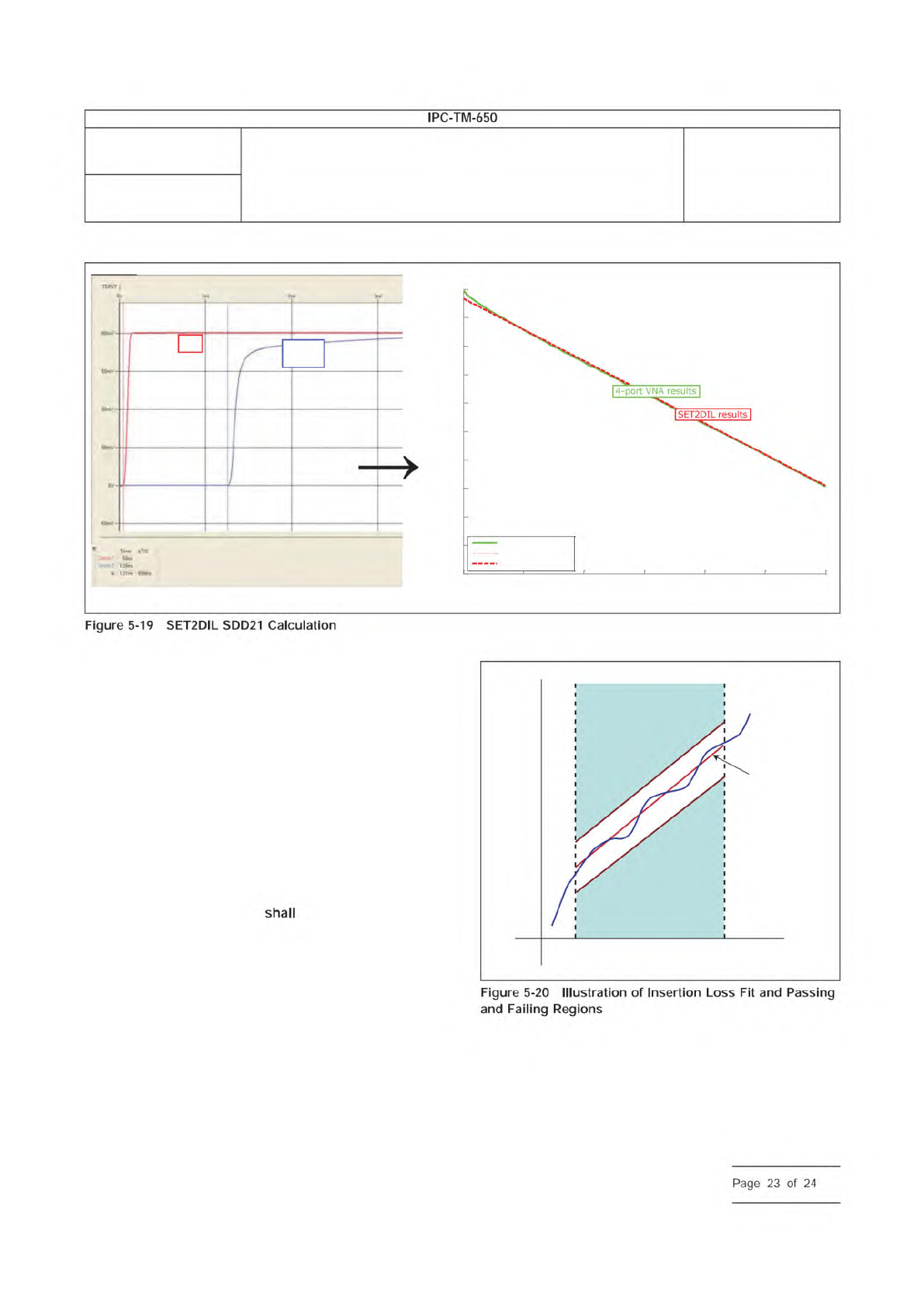
5.5.3 FD Measurement Adherence
The metric used to
determine material ‘‘goodness’’ is insertion loss. Insertion loss
(IL) is defined as the negative of S21 expressed in decibels.
The through scattering parameter, S21, is a direct output from
the VNA or a TDT instrument. The insertion loss fit is used to
determine passing and failing lines. The slope the Insertion
loss fit, ma, can be used as another metric. Figure 5-20 illus-
trates the insertion loss of a line, the respective fit, and limit
regions.
The slope, m
a
, is representative of the average IL obtained
from the test sample. This slope should be less than the
slope, m
spec
, of the pass/fail line that is material dependent.
thru
SET2DIL
TDD21
0 2 4 6 8 10 12
x 10
9
-20
-18
-16
-14
-12
-10
-8
-6
-4
-2
0
VNA vs. SET2DIL (raw and fitted), L1, 100 ohms
Frequency (Hz)
SDD21 Magnitude (dB)
VNA 370HR
SET2DILraw 370HR
SET2DILfit 370HR
IPC-25512-5-20
Failing region high
Insertion
Loss
Fit Line
Failing region low
Frequencyf1
dB
f2
Number
2.5.5.12
Subject
Test Methods to Determine the Amount of Signal Loss on
Printed Boards
Date
07/12
Revision
A
IPC-TM-650
—
Figure
5-19
SET2DIL
SDD21
Calculation
Page
23
of
24