IPC-TM-650 EN 2022 试验方法--.pdf - 第132页
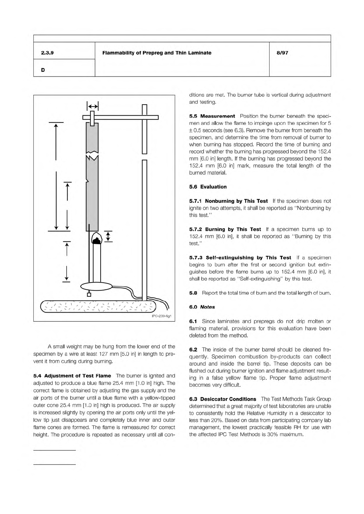
Note: Figure 1 25.4 mm (1 inch) 457 mm (18 inches) 152.4 mm (6 inches) 101.4 mm (4.0 inches) 25.4 mm (1 inch) Laboratory Burner Small Weight IPC-TM-650 Number Subject Date Revision Page 2 of 2 2.3.9 Flammability of Prepr…
IPC-TM-650
The Institute for Interconnecting and Packaging Electronic Circuits
2215 Sanders Road • Northbrook, IL 60062-6135
Material in this Test Methods Manual was voluntarily established by Technical Committees of the IPC. This material is advisory only
and its use or adaptation is entirely voluntary. IPC disclaims all liability of any kind as to the use, application, or adaptation of this
material. Users are also wholly responsible for protecting themselves against all claims or liabilities for patent infringement.
Equipment referenced is for the convenience of the user and does not imply endorsement by the IPC.
Page 1 of 2
IPC-TM-650
TEST
METHODS
MANUAL
1
.0
Scope
This
test
method
is
designed
to
determine
the
degree
of
flame
resistance
of
laminates
less
than
0.5
mm
[0.020
in]
in
thickness,
and
prepreg.
2
.0
Applicable
Documents
Method
2.3.6,
Etching,
Ammonium
Persulfate
Method
2.3.7,
Etching
Ferric
Chloride
Method
2.3.
7.1,
Cupric
Chloride
Etching
Method
2.3.
7.2,
Alkaline
Etching
3
.0
Test
Specimens
3.1
Size
The
test
specimen
shall
be
25.4
mm
[1
.0
in]
wide
by
457
mm
[1
8
in]
long
by
the
thickness
of
the
material
cut
from
the
sheet
such
that
the
457
mm
[1
8
in]
dimension
is
par¬
allel
to
the
warp
yam.
The
specimen
shall
be
marked
152.4
mm
[6
in]
from
one
end.
This
mark
may
be
made
by
cutting
a
small
nick
into
the
edge
of
the
strip.
3.2
Quantity
and
Sampling
A
minimum
of
three
speci¬
mens
shall
be
used
for
each
material
tested
and
each
test
condition,
unless
otherwise
specified.
The
specimens
shall
be
cut
from
various
locations
across
the
width
of
the
sheet
no
closer
than
25.4
mm
[1
.0
in]
from
the
edge
of
the
sheet.
4
.0
Apparatus
or
Material
4.1
Test
Chamber
A
laboratory
hood,
totally
enclosed,
with
a
heat-resistant
glass
window
for
observing
the
test,
shall
be
used.
The
exhaust
fan
shall
be
turned
off
during
the
test,
but
may
be
turned
on
to
clear
out
the
fumes
between
tests.
4.2
Speciman
Holder
Clamping
device
shall
be
provided
within
the
test
chamber
so
that
the
specimen
will
hang
with
its
length
in
a
vertical
position
approximately
coincident
with
the
central
vertical
axis
of
the
test
chamber.
4.3
Laboratory
Burner
A
Bunsen
or
Tirrill
Burner
shall
be
used
having
a
tube
length
of
101.6
mm
[4.0
in]
and
an
inside
diameter
of
9.4
mm
[0.370
in].
The
burner
shall
not
be
equipped
with
end
attachments.
4.4
Gas
Supply
The
gas
supply
shall
be
regulated
and
metered
for
uniform
flow.
The
standard
gas
shall
be
Technical
Number
2.3.9
Subject
Flammability
of
Prepreg
and
Thin
Laminate
Date
8/97
Revision
D
Originating
Task
Group
MIL-P-13949
Test
Methods
Task
Group
(7-1
1b)
Grade
methane.
Natural
gas
having
a
nominal
heat
content
of
1000
BTU
per
cubic
foot
[37
MJ/m3]
or
[37
megajoule
per
cubic
meter]
may
be
substituted.
Other
fuel
gases
such
as
butane,
propane
and
acetylene
may
be
used
provided
they
are
equivalent
in
flame
temperature.
Technical
grade
methane
shall
be
used
for
referee
testing.
4.5
Timer
Stopwatch
or
other
suitable
timing
device
with
a
precision
of
0.5
seconds,
minimum.
4.6
Desiccator
Desiccation
chamber
capable
of
maintain¬
ing
an
atmosphere
of
less
than
30%
RH
at
23℃
[73°F]-
4.7
Conditioning
oven
of
circulating
draft
type
capable
of
maintaining
125
±
2
℃
[257
±
3.6°F].
4.8
Thin
steel
scale
or
template
for
gauging
flame
height.
4.9
Etching
system
capable
of
complete
removal
of
the
metal
cladding.
4.10
Cutting
apparatus
such
as
shears
or
equivalent
equip¬
ment.
5
.0
Procedure
5.1
Specimen
Preparation
Metal-clad
laminates
shall
be
completely
etched
using
standard
industry
practices
(see
IPC-
TM-650,
Methods
2.3.7,
2.3.7.
1
,
or
2.
3.7.2).
Unclad
laminate
and
prepreg
shall
be
tested
in
the
as-is
condition.
Specimens
shall
be
cut
to
size
in
accordance
with
3.1.
5.2
Conditioning
Unless
otherwise
specified,
the
speci¬
mens
shall
be
conditioned
in
standard
ambient
laboratory
conditions
of
23
±
2
℃
[73
±
3.6°F]
and
50
±
5%
RH
for
a
minimum
of
24
hours
prior
to
testing.
5.3
Specimen
Mounting
A
specimen
shall
be
clamped
to
the
clamping
device
in
the
chamber
so
that
the
specimen
hangs
with
its
length
in
a
vertical
position
approximately
coin¬
cident
with
the
central
vertical
axis
of
the
test
chamber.
The
marked
end
of
the
specimen
shall
be
nearest
the
laboratory
burner.
The
lower
end
of
the
specimen
shall
be
at
a
height
25.4
mm
[1.0
in]
more
than
the
height
of
the
laboratory
burner
used
to
provide
the
ignition,
as
shown
in
Figure
1
.
Note:
Figure 1
25.4 mm
(1 inch)
457 mm
(18 inches)
152.4 mm
(6 inches)
101.4 mm
(4.0 inches)
25.4 mm
(1 inch)
Laboratory
Burner
Small Weight
IPC-TM-650
Number
Subject Date
Revision
Page 2 of 2
2.3.9
Flammability
of
Prepreg
and
Thin
Laminate
8/97
D
A
small
weight
may
be
hung
from
the
lower
end
of
the
specimen
by
a
wire
at
least
127
mm
[5.0
in]
in
length
to
pre¬
vent
it
from
curling
during
burning.
5.4
Adjustment
of
Test
Flame
The
burner
is
ignited
and
adjusted
to
produce
a
blue
flame
25.4
mm
[1
.0
in]
high.
The
correct
flame
is
obtained
by
adjusting
the
gas
supply
and
the
air
ports
of
the
burner
until
a
blue
flame
with
a
yellow-tipped
outer
cone
25.4
mm
[1
.0
in]
high
is
produced.
The
air
supply
is
increased
slightly
by
opening
the
air
ports
only
until
the
yel¬
low
tip
just
disappears
and
completely
blue
inner
and
outer
flame
cones
are
formed.
The
flame
is
remeasured
for
correct
height.
The
procedure
is
repeated
as
necessary
until
all
con¬
ditions
are
met.
The
burner
tube
is
vertical
during
adjustment
and
testing.
5.5
Measurement
Position
the
burner
beneath
the
speci¬
men
and
allow
the
flame
to
impinge
upon
the
specimen
for
5
±
0.5
seconds
(see
6.3).
Remove
the
burner
from
beneath
the
specimen,
and
determine
the
time
from
removal
of
burner
to
when
burning
has
stopped.
Record
the
time
of
burning
and
record
whether
the
burning
has
progressed
beyond
the
1
52.4
mm
[6.0
in]
length.
If
the
burning
has
progressed
beyond
the
152.4
mm
[6.0
in]
mark,
measure
the
total
length
of
the
burned
material.
5.6
Evaluation
5.7.1
Nonburning
by
This
Test
If
the
specimen
does
not
ignite
on
two
attempts,
it
shall
be
reported
as
"Nonburning
by
this
test.”
5.7.2
Burning
by
This
Test
If
a
specimen
burns
up
to
152.4
mm
[6.0
in],
it
shall
be
reported
as
"Burning
by
this
test.*'
5.7,3
Self-extinguishing
by
This
Test
If
a
specimen
begins
to
burn
after
the
first
or
second
ignition
but
extin¬
guishes
before
the
flame
burns
up
to
152.4
mm
[6.0
in],
it
shall
be
reported
as
“Self-extinguishing”
by
this
test.
5.8
Report
the
total
time
of
burn
and
the
total
length
of
burn.
6.0
Notes
6.1
Since
laminates
and
prepregs
do
not
drip
molten
or
flaming
material,
provisions
for
this
evaluation
have
been
deleted
from
the
method.
6.2
The
inside
of
the
burner
barrel
should
be
cleaned
fre¬
quently.
Specimen
combustion
by-products
can
collect
around
and
inside
the
barrel
tip.
These
deposits
can
be
flushed
out
during
burner
ignition
and
flame
adjustment
result¬
ing
in
a
false
yellow
flame
tip.
Proper
flame
adjustment
becomes
very
difficult.
6.3
Desiccator
Conditions
The
Test
Methods
Task
Group
determined
that
a
great
majority
of
test
laboratories
are
unable
to
consistently
hold
the
Relative
Humidity
in
a
desiccator
to
less
than
20%.
Based
on
data
from
participating
company
lab
management,
the
lowest
practically
feasible
RH
for
use
with
the
affected
IPG
Test
Methods
is
30%
maximum.
IPC-TM-650
The Institute for Interconnecting and Packaging Electronic Circuits
2215 Sanders Road • Northbrook, IL 60062-6135
Material in this Test Methods Manual was voluntarily established by Technical Committees of the IPC. This material is advisory only
and its use or adaptation is entirely voluntary. IPC disclaims all liability of any kind as to the use, application, or adaptation of this
material. Users are also wholly responsible for protecting themselves against all claims or liabilities for patent infringement.
Equipment referenced is for the convenience of the user and does not imply endorsement by the IPC.
Page 1 of 3
IPC-TM-650
TEST
METHODS
MANUAL
1
.0
Scope
This
test
method
is
designed
to
determine
the
degree
of
flame
resistance
of
metal-clad
or
unclad
laminate.
It
is
intended
for
use
on
laminate
of
thicknesses
0.51
mm
[0.020
in]
and
greater.
2
.0
Applicable
Documents
Method
2.3.6,
Etching,
Ammonium
Persulfate
Method
Method
2.3.7,
Etching,
Ferric
Chloride
Method
Method
2.3.
7.1,
Cupric
Chloride
Etching
Method
Method
2.3.
7.2,
Alkaline
Etching
UL-STD-94,
Flammability
3
.0
Test
Specimens
3.1
Size
Test
specimens
shall
be
127±
0.64
mm
[5.0
±
0.025
in]
in
length
and
12.7
±
0.51
mm
[0.5
±
0.020
in]
in
width
by
the
thickness
being
tested.
Edges
shall
be
smoothed
after
cutting;
any
radius
imparted
to
the
corners
shall
not
exceed
1
.27
mm
[0.05
in].
3.2
Quantity
and
Sampling
Specimens
may
be
taken
par¬
allel
to
either
grain
direction,
unless
otherwise
specified.
Five
specimens
shall
be
prepared
for
each
condition
required.
Reserve
sets
of
five
specimens
should
also
be
prepared
in
the
event
a
retest
is
necessary.
4
.0
Apparatus
or
Material
4.1
Test
Chamber
A
laboratory
hood,
totally
enclosed,
with
a
heat-resistance
glass
window
for
observing
the
test,
shall
be
used.
The
exhaust
fan
shall
be
turned
off
during
the
test,
but
may
be
turned
on
periodically
to
clear
out
the
fumes
between
tests.
4.2
Specimen
Holder
Clamping
device
adjustable
for
ver¬
tical
positioning
of
the
test
specimen
shall
be
provided
within
the
test
chamber
so
that
the
specimen
will
hang
with
its
length
in
a
vertical
position
approximately
coincident
with
the
central
vertical
axis
of
the
test
chamber.
4.3
Laboratory
burner
A
Bunsen
or
Tirrill
Burner
shall
be
used
having
a
tube
length
of
101
.6
mm
[4.0
in]
and
an
inside
diameter
of
9.4
mm
[0.370
in].
The
burner
shall
not
be
Number
2.3.10
Subject
Flammability
of
Laminate
Date
Revision
12/94
B
Originating
Task
Group
MIL-P-13949
Test
Methods
Task
Group
(7-1
1b)
equipped
with
end
attachments.
4.4
Gas
supply
The
gas
supply
shall
be
regulated
and
metered
for
uniform
flow.
The
standard
gas
shall
be
Technical
Grade
methane.
Natural
gas
or
other
fuel
gases
such
as
butane,
propane
and
acetylene
may
be
used,
provided
they
have
a
nominal
heat
content
of
1000
BTU
per
cubic
foot.
Technical
grade
methane
shall
be
used
for
referee
testing.
4.5
Timer
Stopwatch
or
other
suitable
timing
device
with
a
precision
of
0.5
seconds
minimum.
4.6
Desiccator
Desiccation
chamber
capable
of
maintain¬
ing
an
atmosphere
of
less
than
30%
RH
at
23℃
[73°F]-
4.7
Conditioning
oven
of
circulating
draft
type
capable
of
maintaining
125
±
2
℃
[257
±
3.6°F]-
4.8
Thin
steel
scale
or
template
for
gauging
flame
height.
4.9
Etching
system
capable
of
removing
metal-cladding
from
the
laminate.
4.10
Cutting
and
edge
smoothing
apparatus
such
as
shears,
diamond
blade
saw,
or
other
equipment,
and
sanding
or
routing
equipment
for
smoothing.
5
.0
Procedure
5.1
Specimen
Preparation
Metal-clad
laminates
shall
be
completely
etched
using
standard
industry
practices
(see
IPC-
TM-650,
Methods
2.3.7,
2.3.7.
1
,
or
2.
3.
7.
2).
Unclad
lami¬
nates
shall
be
tested
in
the
as-is
condition.
Specimens
shall
be
cut
to
size
and
the
edges
smoothed,
in
accordance
with
3.1.
5.2
Specimen
Conditioning
5.2.1
Specimen
sets
shall
be
conditioned
prior
to
testing
by
exposure
to
standard
laboratory
conditions
of
23
±
2
℃
[73
土
3.6°F]
and
relative
humidity
of
50
±
5%
for
24
hours
minimum.
5.2.2
If
specified,
a
second
set
of
specimens
shall
be
conditioned
for
24
±
2
hours
at
a
temperature
of
1
25
±
2
℃