IPC-TM-650 EN 2022 试验方法--.pdf - 第721页
a. Contamination on the insulating surfa ce of the board such as l int, solder splines, or water droplets from the condition- ing c hamber. b. Incompletely etched patterns that decrease the insulating sp ace be twe en co…
5.5.6
Upon completion of the 168 hours, turn off the bias
and open the test chamber and allow the test specimens to
return to laboratory ambient conditions.
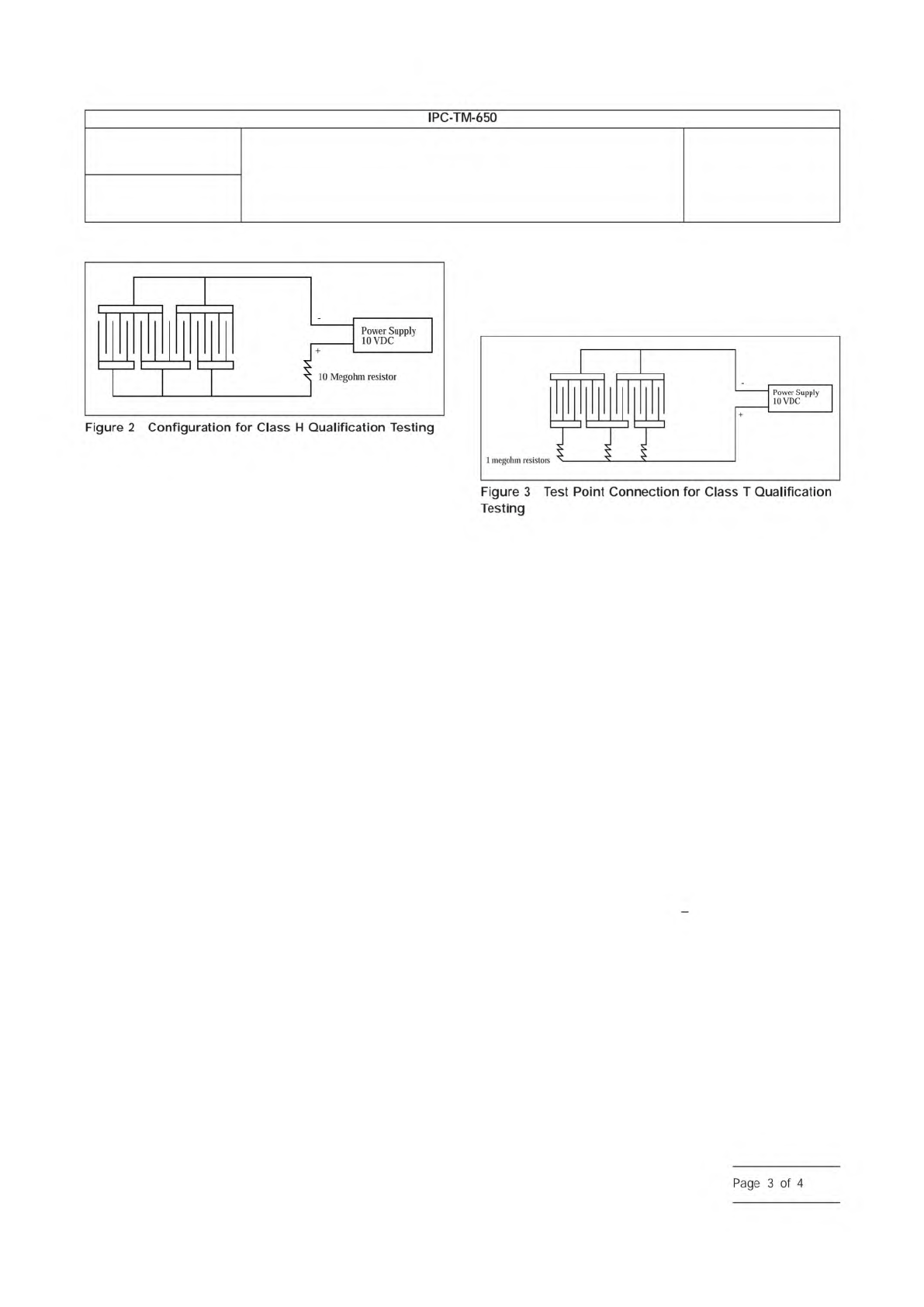
5.6 Class H – Measurements/Evaluation
5.6.1
Upon specimen stabilization at laboratory ambient
temperature, take the resistance measurements, as specified
in 5.5.1, with 10 VDC and record.
5.6.2
Examine the test specimens with 10X magnification
with backlighting for electrochemical migration.
5.7 Class T – Test Chamber Method
5.7.1
Prior to testing, take insulation resistance measure-
ments of the test specimens using 45 -100 VDC. This step will
ensure that the resistance measurements are sufficient to pro-
ceed with testing.
5.7.2
Place the test specimens into the test chamber and
route the wires through the porthole of the test chamber and
seal, if necessary.
5.7.3
Set the chamber’s parameters for 85 °C [185 °F] with
85% relative humidity minimum. Close the chamber doors and
activate the test chamber.
5.7.4
Allow the test specimens to stabilize at test conditions
for 96 hours (four days).
5.7.5
After the 96-hour (four days) stabilization period at test
conditions, take measurements of initial insulation resistance
as specified in 5.7.1 with 45 -100 VDC.
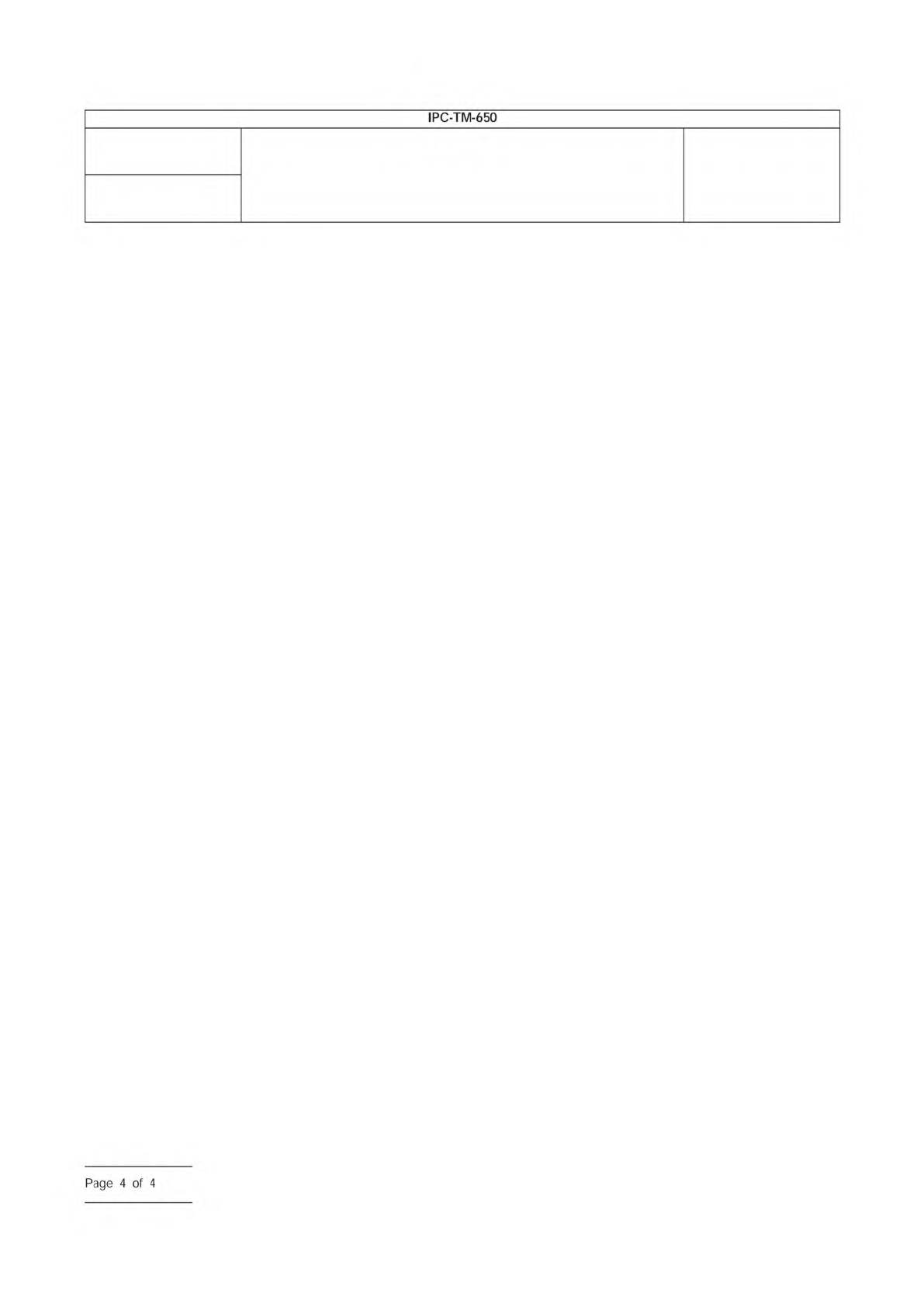
5.7.6
After obtaining the measurements, connect each test
point as specified in 5.3.1 and 5.3.2 to a 1-megohm resistor
before the positive terminal of power supply. (See Figure 3 for
configuration of qualification testing.) Apply the bias voltage of
10VDC. The test polarity shall be the same as the measure-
ment polarity stated in 5.7.1.
5.7.7
Allow the specimens to remain in the test chamber an
additional 404 hours (500 hours total test time).
5.8 Class T – Measurements/Evaluations
5.8.1
Upon completion of the 500 hours (21 days), discon-
nect the power supply and repeat the measurements as
stated in 5.7.5 with the specimens under test conditions.
5.8.2
The chamber is then turned off and the specimens are
removed from the test chamber and visually inspected with
backlighting at 10X magnification for electrochemical migra-
tion.
5.8.3
The individual resistance measurements obtained at
96 hours and 500 hours shall be averaged using the following
calculation. These initial and final average insulation resistance
readings shall then be reported.
IR
avg
= 10
[
1
N
Σ
1
N
log IR
i
]
Where:
N = Number of test points (12 nominal)
IR
i
= Individual insulation resistance measurements
5.8.4
Where an assignable cause can be found, exception-
ally low insulation resistance readings can be excluded from
calculating the average value, provided that 11 (of the original
12) measurements are included in the average. Such assign-
able causes are attributable to the laminate itself or to the
process used to produce the printed board. They include:
IPC-2614-2
IPC-2614-3
Number
2.6.14
Subject
Solder Mask - Resistance to Electrochemical Migration
Date
03/07
Revision
D
IPC-TM-650
10
Megohm
resistor
Power
Supply
10VDC
Figure
2
Configuration
for
Class
H
Qualification
Testing
1
megohm
resistors
Power
Supply
10VDC
Figure
3
Test
Point
Connection
for
Class
T
Qualification
Testing
Page
3
of
4
a. Contamination on the insulating surface of the board such
as lint, solder splines, or water droplets from the condition-
ing chamber.
b. Incompletely etched patterns that decrease the insulating
space between conductors by more than the amount
allowed in the appropriate design requirements drawing.
c. Scratched, cracked or obviously damaged insulation
between conductors.
6 Notes
6.1
Protective coatings are helpful in preventing electro-
chemical migration, but there is no assurance that the protec-
tion is complete unless the coating is adequately bonded to a
good clean board.
Number
2.6.14
Subject
Solder Mask - Resistance to Electrochemical Migration
Date
03/07
Revision
D
IPC-TM-650
Page
4
of
4
IPC-B-25
IPC-B-25A
IPC-6012A
IPC-9201
ASTM D-257-93
Figure 1 IPC-B-25A Test Board
Material in this Test Methods Manual was voluntarily established by Technical Committees of IPC. This material is advisory only
and its use or adaptation is entirely voluntary. IPC disclaims all liability of any kind as to the use, application, or adaptation of this
material. Users are also wholly responsible for protecting themselves against all claims or liabilities for patent infringement.
Equipment referenced is for the convenience of the user and does not imply endorsement by IPC.
Page 1 of 3
ASSOCIATION
CONNECTING
/
ELECTRONICS
INDUSTRIES
221
5
Sanders
Road
Northbrook,
IL
60062-61
35
IPC-TM-650
TEST
METHODS
MANUAL
1
Scope
This
test
method
provides
a
means
to
assess
the
propensity
for
surface
electrochemical
migration.
This
test
method
can
be
used
to
assess
soldering
materials
and/or
processes.
2
Applicable
Documents
2.1
IRC
Multipurpose
Test
Board
Multipurpose
Test
Board
Qualification
and
Performance
Specification
for
Rigid
Printed
Boards
Surface
Insulation
Resistance
Handbook
2.1
American
Society
for
Testing
and
Materials
(ASTM)
Standard
Test
Methods
for
DC
Resistance
or
Conductance
of
Insulating
Materials
3
Test
Specimens
IPC-B-25
(B
or
E
pattern)
or
IPC-B-25A
(D
pattern)
test
boards
shall
be
used,
with
conductor
line
widths
and
spacings
of
0.318
mm
[0.01250
in].
The
method
of
manufacture
should
provide
optimized
conductor
edge
definition
(refer
to
the
Class
2
and
3
conductor
width
require¬
ments
in
IPC-601
2).
The
finished
test
boards
should
be
untreated,
bare
copper,
unless
another
surface
finish
is
part
of
the
evaluation.
Figure
1
shows
the
IPC-B-25A
test
board;
the
D
pattern
is
identical
to
the
IPG-B-25
B
or
E
pattern.
For
pro¬
cess
evaluation,
the
test
pattern
board
should
be
made
using
the
same
substrate
material
as
will
be
used
in
practice
to
duplicate
actual
working
conditions.
4
Equipment/Apparatus
4.1
Test
Chamber
A
temperature/humidity
chamber
capable
of
producing
an
environment
of
40℃
±
2
℃
[104
±
36F],
93%
土
2%
RH,
65℃
±
2
℃
[149
±
3.6°F],
88.5%
±
3.5%
RH,
or
85℃
+
2
℃
[185
土
3.6°F],
88.5%
土
3.5%
RH
and
allowing
test
boards
to
be
electrically
biased
and
mea¬
sured
without
being
opened
under
these
temperature
and
humidity
conditions
is
used.
Number
2.6.14.1
Subject
Electrochemical
Migration
Resistance
Test
Date
Revision
09/00
Originating
Task
Group
Electrochemical
Migration
Task
Group
IPG-261
41-1
with
a
range
up
to
1012ohm
and
capable
of
yielding
an
accu¬
racy
of
+
5%
at
101°ohm
with
an
applied
potential
of
100
VDC
(10%
tolerance);
standard
resistors
should
be
used
for
routine
calibration.
4.3
Power
Supply
Equipment
capable
of
providing
10
VDC
at
100
pA,
with
a
10%
tolerance,
shall
be
used.
4.4
Current-Limiting
Resistors
Use
one
1
03
6
ohm
resistor
in
each
current
path.
This
equates
to
three
current-limiting
resistors
for
each
5-point
comb
pattern.
Note
that
some
test
equipment
has
the
current
limiting
resistors
built
into
the
test¬
ing
system.
4.5
Connecting
Wire
Use
PTFE-insulated,
solid¬
conductor,
copper
wire,
or
equivalent.
(See
IPC-9201
Surface
Insulation
Resistance
Handbook.)
4.2
Measuring
Equipment
High
resistance
measuring
equipment,
equivalent
to
that
described
in
ASTM
D-257-93,