创建组件识别数据的方法.pdf - 第10页
10/178 IM-SMT-VSNDI C-0002 -000 Items to be set Set value Explanation Lead Group N Sets the number of Lead Group (1 or 2) Ruler Offset N Sets th e offs et amount for the detect ion line in the N direction . Items to be s…
9/178
IM-SMT-VSNDIC-0002-000
Lead width: width 1
Lead pitch: pitch 1
Number of the leads: n1
<< Group 2: Right-side group in N direction >>
Reference lead position X2
Reference lead position Y2
Lead length: length 2
Lead width: width 2
Lead pitch: pitch 2
Number of the leads: n2
As shown in Figure 6, the groups are specified as Group1 and Group 2, from left to right in the
N/S direction, and from top to bottom in the W/E direction.
The definitions are made in the same way for the S, E and W directions.
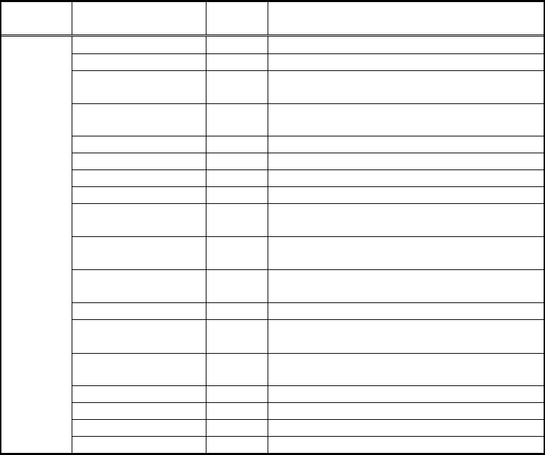
This is how to define the component shape. Detailed setting items for the component data are
as follows:
<< Details of the component data>>
Items to be set
Set
value
Explanation
Alignment Group Sets the component category.
Alignment Type Sets the component type.
Comp. Threshold
Sets the threshold value or the level
difference.
Comp. Tolerance
Specifies the shape tolerance as a
percentage.
Search Area (mm) Sets the range of the detection.
Body Size X (mm) Sets the size of the outer edge.
Body Size Y (mm) Sets the size of the outer edge.
Body Size Z (mm) Sets the size of the outer edge.
Cntr. Offset X (mm)
Sets the offset amount in the X direction
from the center position.
Cntr. Offset Y (mm)
Sets the offset amount in the Y direction
from the center position.
Cntr. Offset R (mm)
Sets the offset amount of the angle of
rotation.
Ruler Width
Algorithm
Selects the recognition algorithm when
using a special algorithm.
Base Alignment
Selects the basic component type when
using a special algorithm.
Vision Option Sets option parameter 1.
Vision Option 2 Sets option parameter 2.
Vision Option 3 Sets option parameter 3.
Common
Data
Vision Option 4 Sets option parameter 4.
10/178
IM-SMT-VSNDIC-0002-000
Items to be set
Set
value
Explanation
Lead Group N
Sets the number of Lead Group (1 or 2)
Ruler Offset N
Sets the offset amount for the detection line in
the N direction.
Items to be set
(Group 1)
Set
value
Items to be set
(Group 2)
Set
value
Explanation
Lead Number:
1N
Lead Number:
2N
Sets the number of
leads.
Reflect LL.:
1N (mm)
Reflect LL.:
2N (mm)
Sets the lead length of
the upper lead(s) on
the image.
Lead Width:
1N (mm)
Lead Width:
2N (mm)
Sets the width of the
lead for the upper
lead(s).
Lead Pitch:
1N (mm)
Lead Pitch:
2N (mm)
Sets the pitch for the
upper lead(s).
Find Pos X:
1N (mm)
Find Pos X:
2N (mm)
Sets the reference
position for the upper
lead(s).
N
direction
Find Pos Y:
1N (mm)
Find Pos Y:
2N (mm)
Items to be set
Set
value
Explanation
Lead Group S
Sets the number of Lead Group (1 or 2)
Ruler Offset S
Sets the offset amount for the detection line in
the S direction.
Items to be set
(Group 1)
Set
value
Items to be set
(Group 2)
Set
value
Explanation
Lead Number:
1S
Lead Number:
2S
Sets the number of
leads.
Reflect LL.:
1S (mm)
Reflect LL.:
2S (mm)
Sets the lead length of
the lower lead(s) on
the image.
Lead Width:
1S (mm)
Lead Width:
2S (mm)
Sets the width of the
lead for the lower
lead(s).
Lead Pitch:
1S (mm)
Lead Pitch:
2S (mm)
Sets the pitch for the
lower lead(s).
Find Pos X:
1S (mm)
Find Pos X:
2S (mm)
Sets the reference
position for the lower
lead(s).
S
direction
Find Pos Y:
1S (mm)
Find Pos Y:
2S (mm)
Items to be set
Set
value
Explanation
Lead Group E
Sets the number of Lead Group (1 or 2)
E
direction
Ruler Offset E
Sets the offset amount for the detection line in
the E direction.
11/178
IM-SMT-VSNDIC-0002-000
Items to be set
(Group 1)
Set
value
Items to be set
(Group 2)
Set
value
Explanation
Lead Number:
1E
Lead Number:
2E
Sets the number of
leads.
Reflect LL.:
1E (mm)
Reflect LL.:
2E (mm)
Sets the lead length of
the lead(s) on the right
on the image.
Lead Width:
1E (mm)
Lead Width:
2E (mm)
Sets the width of the
lead for the lead(s) on
the right.
Lead Pitch:
1E (mm)
Lead Pitch:
2E (mm)
Sets the pitch for the
lead(s) on the right.
Find Pos X:
1E (mm)
Find Pos X :
2E (mm)
Sets the reference
position for the lead(s)
on the right.
Find Pos Y:
1E (mm)
Find Pos Y:
2E (mm)
Items to be set
Set
value
Explanation
Lead Group W
Sets the number of Lead Group (1 or 2)
Ruler Offset W
Sets the offset amount for the detection line in
the W direction.
Items to be set
(Group 1)
Set
value
Items to be set
(Group 2)
Set
value
Explanation
Lead Number:
1W
Lead Number:
2W
Sets the number of
leads.
Reflect LL.:
1W (mm)
Reflect LL.:
2W (mm)
Sets the lead length for
the lead(s) on the left
on the image.
Lead Width:
1W (mm)
Lead Width:
2W (mm)
Sets the width of the
lead for the lead(s) on
the left.
Lead Pitch:
1W (mm)
Lead Pitch:
2W (mm)
Sets the pitch for the
lead(s) on the left.
Find Pos X:
1W (mm)
Find Pos X :
2W (mm)
Sets the reference
position for the lead(s)
on the left.
W
direction
Find Pos Y:
1W (mm)
Find Pos Y:
2W (mm)
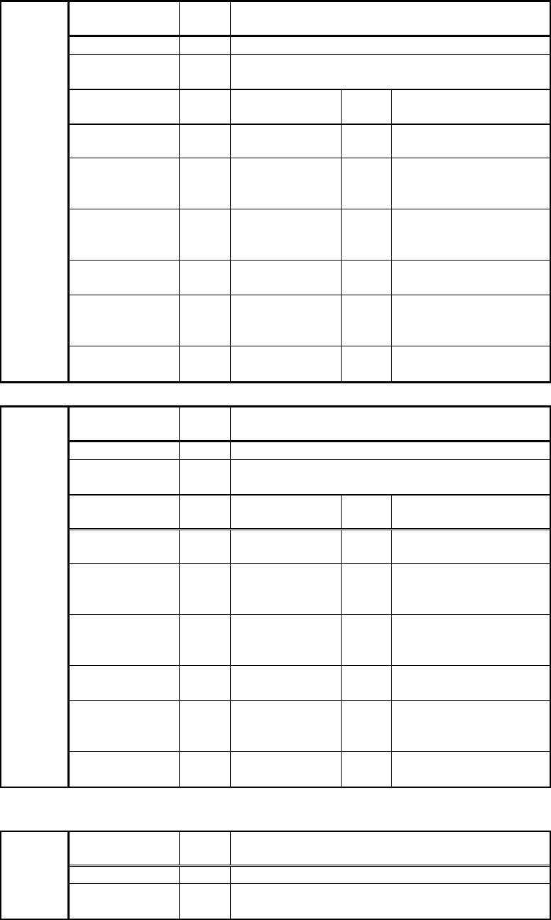
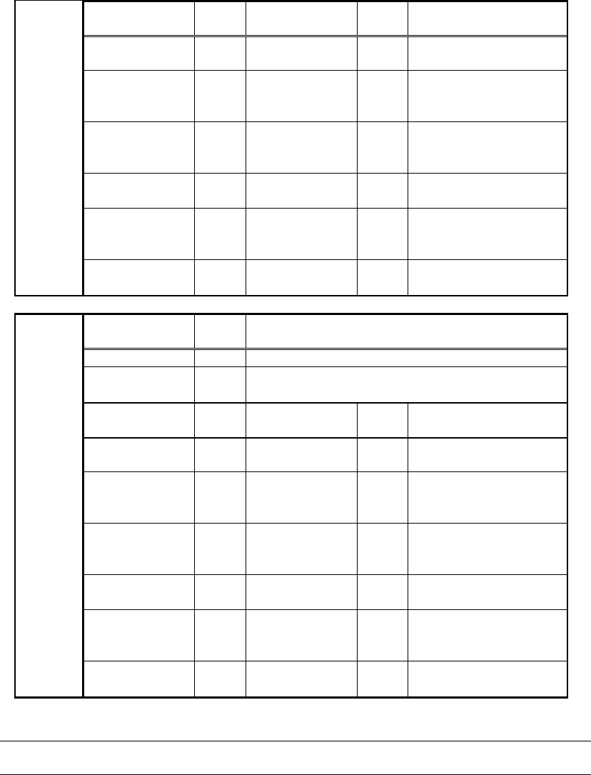
Table 2
Caution:
In Table 2, the reference lead positions are expressed as the Find Pos.