创建组件识别数据的方法.pdf - 第17页
17/178 IM-SMT-VSNDI C-0002 -000 Items to be set Set value Items to be set Set value Lead Num ber 1W vnum Lead Num ber 2W 0 Reflect LL 1W (mm) length Reflect LL 2W (mm) 0 Lead W idth 1W (mm) width Lead W idth 2W (mm) 0 Le…
16/178
IM-SMT-VSNDIC-0002-000
Items to be set Set value
Vision Option 3 0
Vision Option 4 0
Table 4
<<N direction data>>
Items to be set Set value
Lead group N 1
Ruler Offset N 3
Items to be set Set value Items to be set Set value
Lead Number 1N hnum Lead Number 2N 0
Reflect LL 1N (mm)
length Reflect LL 2N (mm) 0
Lead Width 1N (mm)
width Lead Width 2N (mm) 0
Lead Pitch 1N (mm)
pitch Lead Pitch 2N (mm) 0
Find Pos X 1N (mm) -hposx Find Pos X 2N (mm) 0
Find Pos Y 1N (mm) hposy Find Pos Y 2N (mm) 0
<<S direction data>>
Items to be set Set value
Lead group S 1
Ruler Offset S 3
Items to be set Set value Items to be set Set value
Lead Number 1S hnum Lead Number 2S 0
Reflect LL 1S (mm)
length Reflect LL 2S (mm) 0
Lead Width 1S (mm)
width Lead Width 2S (mm) 0
Lead Pitch 1S (mm)
pitch Lead Pitch 2S (mm) 0
Find Pos X 1S (mm)
- hposx Find Pos X 2S (mm) 0
Find Pos Y 1S (mm)
- hposy Find Pos Y 2S (mm) 0
<<E direction data>>
Items to be set Set value
Lead group E 1
Ruler Offset E 3
Items to be set Set value Items to be set Set value
Lead Number 1E vnum Lead Number 2E 0
Reflect LL 1E (mm)
length Reflect LL 2E (mm) 0
Lead Width 1E (mm)
width Lead Width 2E (mm) 0
Lead Pitch 1E (mm)
pitch Lead Pitch 2E (mm) 0
Find Pos X 1E (mm)
- vposx Find Pos X 2E (mm) 0
Find Pos Y 1E (mm)
vposy Find Pos Y 2E (mm) 0
<<W direction data>>
Items to be set Set value
Lead group W 1
Ruler Offset W 3
17/178
IM-SMT-VSNDIC-0002-000
Items to be set Set value Items to be set Set value
Lead Number 1W vnum Lead Number 2W 0
Reflect LL 1W (mm)
length Reflect LL 2W (mm) 0
Lead Width 1W (mm)
width Lead Width 2W (mm) 0
Lead Pitch 1W (mm)
pitch Lead Pitch 2W (mm) 0
Find Pos X 1W (mm)
vposx Find Pos X 2W (mm) 0
Find Pos Y 1W (mm)
vposy Find Pos Y 2W (mm) 0
Table 5
Caution:
In Table 5, the reference lead positions are displayed as the Find Pos.
In this way, the component data can normally be created just by specifying the minimum
necessary data.
1.4 Precautions concerning the component data definitions
This section describes points to notice on component data setting.
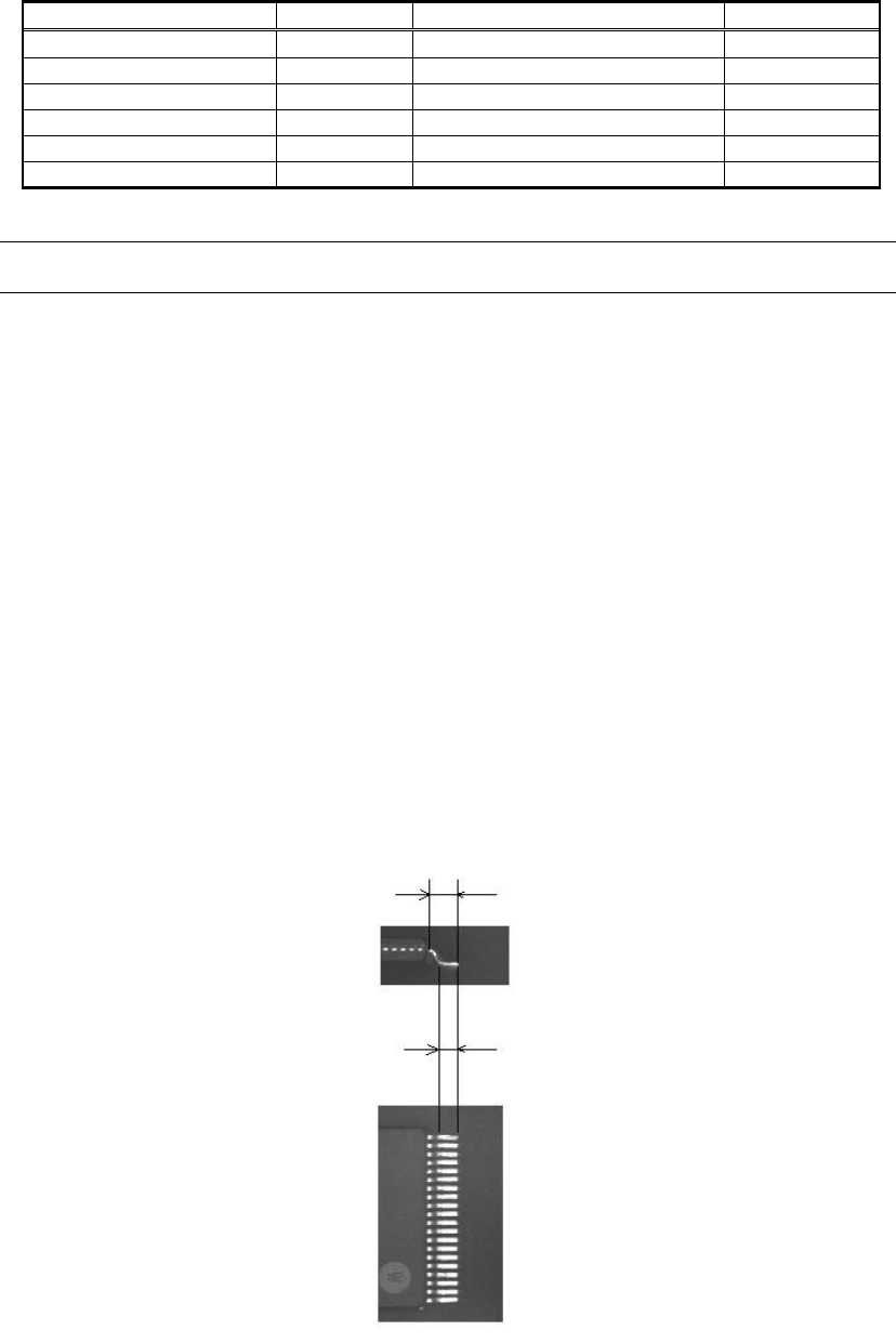
1.4.1. ReflectLL.
Caution is required in recognizing to the lead length. When the component is read as an
image, the lead may appear different in the image from the actual image.
The bent parts of the gull-wing shaped leads look black in the image and are hard to be
recognized.
In this case, it is necessary to specify the data using the shape that is visible on the image,
rather than the actual component shape. As can be expected from the item name “ReflectLL.”
on the data definition screen, the length of the portion that is visible in the image is supposed
to be set on the screen.
Figure 10
Actual lead length
Reflecting lead length
18/178
IM-SMT-VSNDIC-0002-000
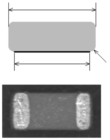
1.4.2. Component sizes (chip component)
When the chip component (capacitors) and other components whose tip is rounded, the
component size on the image may be different from the actual component size.
In this case, the size on the image should be set.
Figure 11
2. Details of the component data setting
As already mentioned, it is possible to create the data for the standard components with the
minimum necessary data.
In the component recognition mode, the components are divided into the groups shown below
and the data is created for each mode.
<IC components>
1) 2-pin components
2) Mini-mold transistors / SOTs
3) Power transistors
4) SOP Recognition mode
5) QFP Recognition mode
6) SOJ Recognition mode
7) PLCC Recognition mode
8) Off Lead
<Connector components>
1) Single-direction Connector recognition mode
Actual component size
Set component size
The fig
ure seen from the side of the component
This part looks dark
The image of the component seen from the bottom surface