创建组件识别数据的方法.pdf - 第106页
106/178 IM-SMT-VSNDI C-0002 -000 Items to be set Set value Ruler W idth 1 Algorithm S pec ial 1 Base Alignm ent Flip chip Vision Option 1 0 Vision Option 2 0 Vision Option 3 0 Vision Option 4 0 Items to be set Set value …
105/178
IM-SMT-VSNDIC-0002-000
Trace retry 0: No 1: Yes
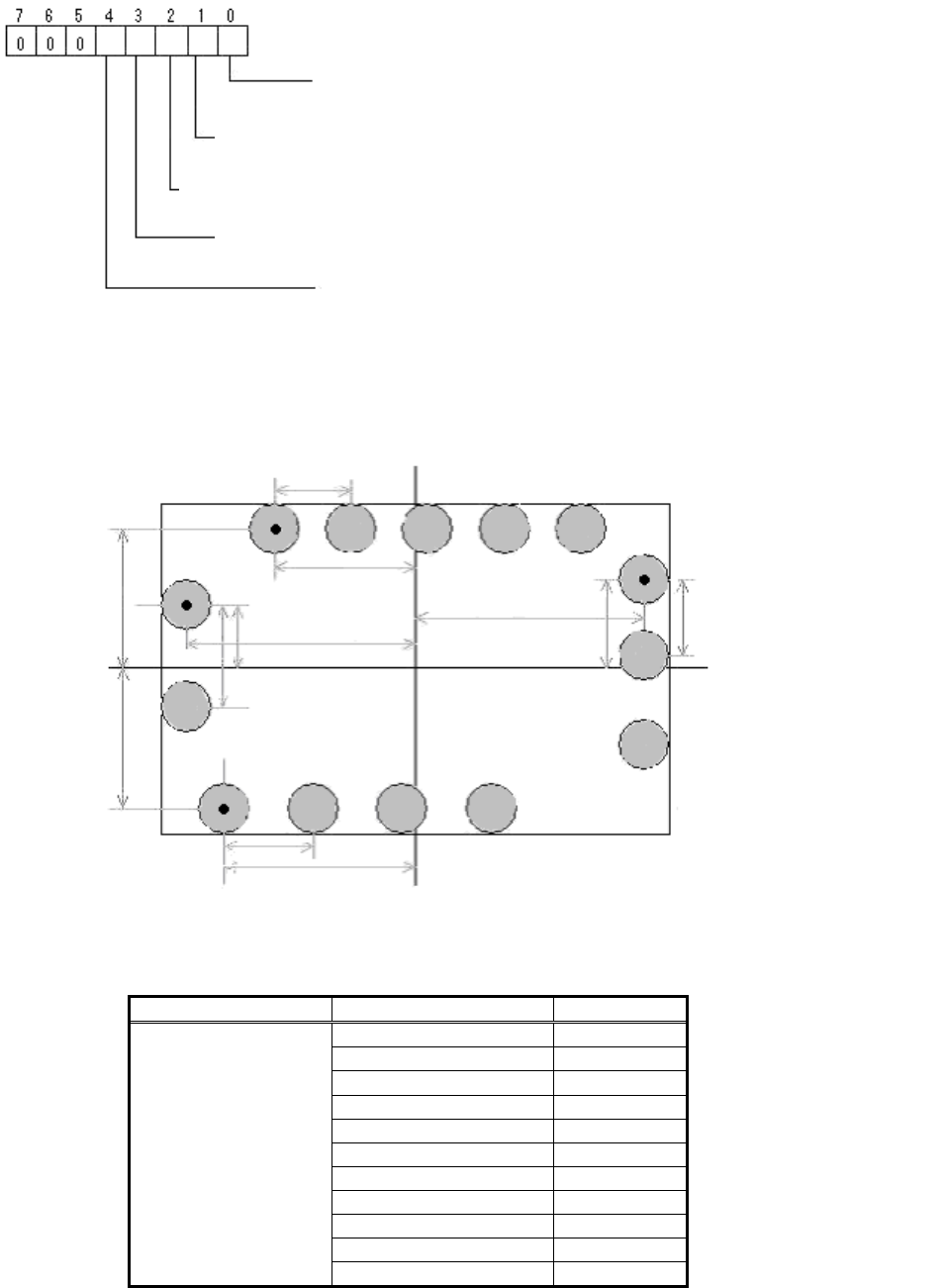
Note *4: The ball diameter is set for the LeadWidth.
Note *5: The center of gravity position of the leads targeted for detection is set as the offset
position from the component center.
Figure 76
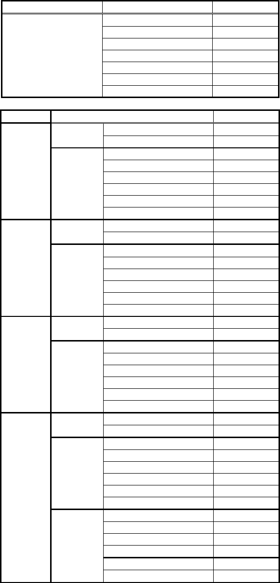
The following is the actual example.
Items to be set Set value
Alignment Group Special
Alignment Type Special
Comp. Threshold 0
Comp. Tolerance 30
Search Area (mm) 2.0
Body Size X (mm) 10.0
Body Size Y (mm) 10.0
Body Size Z (mm) 1.0
Cntr. Offset X (mm) 0.0
Cntr. Offset Y (mm) 0.0
Common
Data
Cntr. Offset R (mm) 0.0
Bit position
Pitch check :(0: Not run 1: Run)
))
Binarization method when threshold value is 0:
(0:
Automatic
binarization
,
1: P
-
tile
b
inarization
)
Lead position check: ( 0: Not run, 1: Run)
*See ”Appendix 4. Lead position check
”
(Checks to see whether the lead is within the range by using the pitch x tolerance.
If a check is performed, the pitch must be
entered even if the Lead Number is 1.)
Method for setting parameter for distance between leads /corners
(
0: New
,
1: Previous
)
Lead Pitch
N1
Find Pos Y N1
Find Pos Y S
1
Find Pos
X S
1
Find Pos Y E1
Find Pos
X
E1
Find Pos
X N
1
Find Pos Y W1
Find Pos X W1
Lead Pitch E1
Lead Pitch W1
Lead Pitch S1
106/178
IM-SMT-VSNDIC-0002-000
Items to be set Set value
Ruler Width 1
Algorithm Special 1
Base Alignment Flip chip
Vision Option 1 0
Vision Option 2 0
Vision Option 3 0
Vision Option 4 0
Items to be set Set value
Lead Group N 1
Common
Ruler Offset N 0
Lead Number: 1N
10
Reflect LL.: 1N (mm) 0.0
Lead Width: 1N (mm) 0.7
Lead Pitch: 1N (mm) 1.0
Find Pos X: 1N (mm) -4.5
N
direction
Group
1
Find Pos Y: 1N (mm) 4.5
Lead Group S 1
Common
Ruler Offset S 0
Lead Number
: 1S 10
Reflect LL.: 1S (mm) 0.0
Lead Width: 1S (mm) 0.7
Lead Pitch: 1S (mm) 1.0
Find Pos X: 1S (mm) -4.5
S
direction
Group
1
Find Pos Y: 1S(mm) -4.5
Lead Group E 1
Common
Ruler Offset E 0
Lead Number
: 1E 10
Reflect LL.: 1E (mm) 0.5
Lead Width: 1E (mm) 0.7
Lead Pitch: 1E (mm) 1.0
Find Pos X: 1E (mm) 4.5
E
direction
Group
1
Find Pos Y: 1E(mm) 4.5
Lead Group W 2
Common
Ruler Offset W 0
Lead Number: 1W
3
Reflect LL.: 1W (mm) 0.0
Lead Width: 1W (mm) 0.7
Lead Pitch: 1W (mm) 1.0
Find Pos X: 1W (mm) -4.5
Group
1
Find Pos Y: 1W(mm) 4.5
Lead Number: 2W
1
Reflect LL.: 2W(mm) 0.0
Lead Width: 2Wmm) 0.7
Lead Pitch: 2W(mm) 0.0
Find Pos X: 2W(mm) -4.5
W
direction
Group
2
Find Pos Y: 2Wmm) -4.5
Table 73
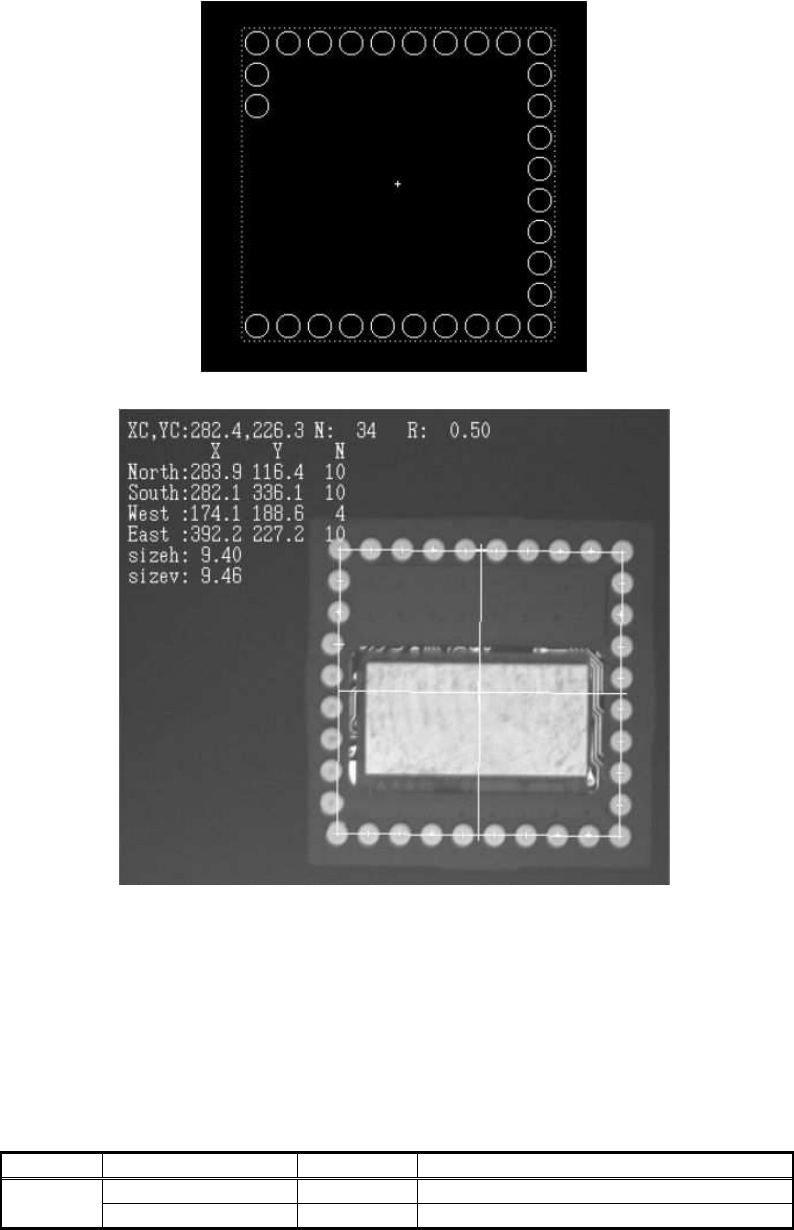
Figure 77 is the shape defined by the component definition. It is defined to recognize only the
pads that are arranged in a regular pattern.
Also, the pads on each corner are doubly defined by each side.
Figure 78
is the recognition
107/178
IM-SMT-VSNDIC-0002-000
result obtained by the data.
Figure 77
Figure 78
2.10.6 Flip-chip recognition : Special 2 and 3
These recognition modes are used for chips that have the balls placed in a random pattern.
A file containing definitions for each ball position is use for recognition.
With Special 2, the contour tracing based on binarization is used for recognition.
With Special 3, recognition is performed by matching the individual balls.
<< Flip-chip Special 2 &3 >>
Items to be set Set value
Explanation
Alignment Group Special Sets the component category.
Common
Data
Alignment Type Special Sets the component type.