创建组件识别数据的方法.pdf - 第29页
29/178 IM-SMT-VSNDI C-0002 -000 2.3. P-T r <Items to be set f or P-T r> Items to be set S et value Explanation Alignment Group IC Sets the com ponent categor y . Alignment T ype P-TR Sets the component t ype. Comp.…
28/178
IM-SMT-VSNDIC-0002-000
2.2.2. Mini-mold transistor / SOTs Special –(4)
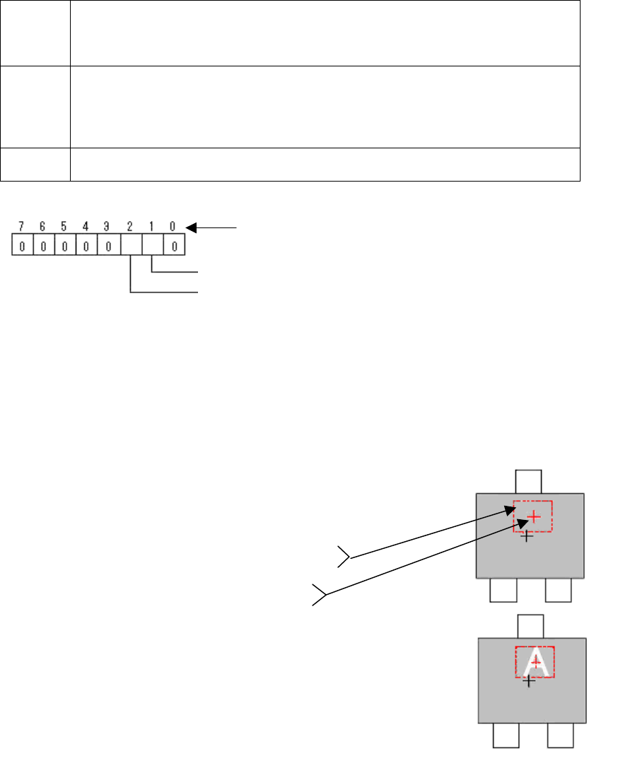
Check Upside-Down (Dispersion)
The top surface and the bottom surface of the components is identified by checking the
variation of the brightness (dispersion) of the determination range.
It is applicable for the components with the characters printed on the molded area of the
pickup surface.
Option 1
Threshold of 3-sigma
Sets the threshold of the value of the brightness variation (3sigma) in the
determination range.
The value becomes larger as the brightness variation becomes large.
Option 2
Threshold of Average
Sets the lower limit of the average brightness (Ave) in the determination area.
It is available only when “Dispersion” is specified as “NG condition”.
It is used when over-determination occurs due to the variant set for
determination.
Option 3
Judgement Flag (Some old version software may not be equipped with this
function.)
Table 16
Specify the determination range in the Lead Group 1 in W direction.
(If it is necessary to offset to the E direction, set to East.)
Figure 18
Bit position
Determinati
on range Offset Enable: (0: Disable, 1: Enable)
NG condition: (0:Dispersion, 1: Non Dispersion)
- Dispersion: When the variance of the brightness in the
determination range is larger than threshold, it is determined
to be an error.
- Non Dispersion: When the variance of the brightness in the
determination range is smaller than threshold, it is
determined to be an error.
- Number of the Lead Group W: 1
- Number of the leads W1: 0
- Lead pitch W1: 0
- Lead width W1: Size of the determination range Y
- Reflect LL W1: Size of the determination range X
- Find Pos X W1: Determination range offset X
- Find Pos Y W1: Determination range offset Y
Dispersion: Small
Dispersion: Large

29/178
IM-SMT-VSNDIC-0002-000
2.3. P-Tr
<Items to be set for P-Tr>
Items to be set Set value
Explanation
Alignment Group IC Sets the component category.
Alignment Type P-TR Sets the component type.
Comp. Threshold
Sets the detection level difference for lead
detection.
(See “Appendix 2. Detection level
differences used to detect leads (threshold value)”)
Comp. Tolerance
Specifies the tolerance of the lead pitch as a
percentage.
Search Area (mm) Sets the range of the detection.
Body Size X (mm) Sets the size of the outer edge.
Body Size Y (mm) Sets the size of the outer edge.
Body Size Z (mm) Sets the size of the outer edge.
Cntr. Offset X (mm)
Sets the offset amount in the X direction from the
center position.
Cntr. Offset Y (mm)
Sets the offset amount in the Y direction from the
center position.
Cntr. Offset R (mm) Sets the offset amount of the angle of rotation.
Ruler Offset N
Sets the offset amount for the detection line in the
N direction.
Ruler Offset S
Sets the offset amount for the detection line in the
S direction.
Ruler Width
Lead Number : N
Sets the number of leads in the N direction.
Reflect LL.: N (mm)
Sets the lead length on the image.
Lead Width: N (mm)
Sets the width of the lead.
Lead Pitch: N (mm)
Sets the pitch in the N direction. (Set to 0 when
there is only one lead.)
Lead Number : S
Sets the number of leads in the S direction.
Reflect LL.: S (mm)
Sets the lead length on the image.
Lead Width: S (mm)
Sets the width of the lead.
Lead Pitch: S (mm)
Sets the pitch in the S direction. (Set to 0 when
there is only one lead.)
Table 17
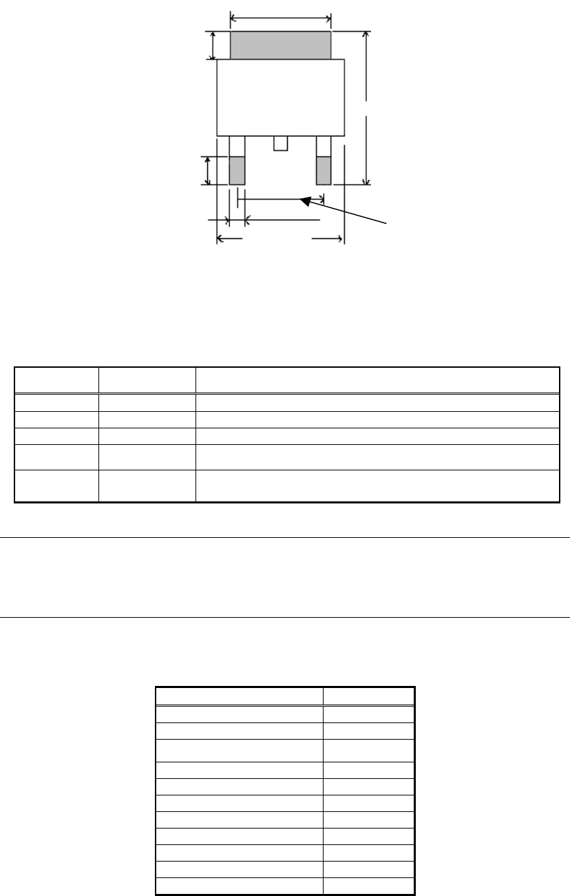
This is the recognition mode for power transistors with leads in the N and S directions. It can
be used not only for power transistors, but also for recognition of any components whose
upper and lower lead width and lead lengths are different.
The number of the lead, lead pitch, lead width and lead length can be defined separately for
the N and S directions. Though the upper and lower directions do not need to be symmetrical,
the left and right directions must be symmetrical.
30/178
IM-SMT-VSNDIC-0002-000
Figure 19
[Recognition check items ]
Items Yes / No Notes
Body Size May exist Only the outer edge dimension Y is checked.
(Note 1)
Lead pitch Yes The pitch in the direction with one lead is not checked.
Lead width
No
Reflect LL No
Find Pos Yes
Checks the lead tip position using [outer edge
dimension Y x tolerance] as check range.
(Note 2)
Table 18
Note:
1. This function performs a check only when the check function is validated in the
application software. (Some versions are not equipped with this function.)
2. See “Appendix 4. Lead position check” for the details of the “Lead position check”
function.
Table 19 shows the example of actual settings and the recognition results.
<Items to be set for Power Transistor>
Items to be set Set value
Alignment Group IC
Alignment Type P-Tr
Comp. Threshold 40
Comp. Tolerance 30
Search Area (mm) 2.0
Body Size X (mm) 6.5
Body Size Y (mm) 9.5
Body Size Z (mm) 2.3
Cntr. Offset X (mm) 0.0
Cntr. Offset Y (mm) 0.0
Cntr. Offset R (mm) 0.0
Lead Width N
Lead Length N
Body Size Y
Lead Length S
Lead Width S
Body Size X
Pitch S