创建组件识别数据的方法.pdf - 第93页
93/178 IM-SMT-VSNDI C-0002 -000 [Recognition check items ] Items Y es / No Notes Body Size No Ball pitch Y es Table 65 The following is the actual example of the s etting and the recognitio n result. Recognition is pr ef…
92/178
IM-SMT-VSNDIC-0002-000
2.10.2 BGA Recognition mode
<< Items to be set for BGAs>>
Items to be set Set value
Explanation
Alignment Group Ball Sets the component category.
Alignment Type BGA Sets the component type.
Comp. Tolerance
Specifies the tolerance of the ball pitch as a
percentage.
Search Area (mm) Sets the range of the detection.
Body Size X (mm) Sets the size of the outer edge.
Body Size Y (mm) Sets the size of the outer edge.
Body Size Z (mm) Sets the size of the outer edge.
Ball number N
Sets the number of BGA ball rows in the
horizontal direction.
Ball number E
Sets the number of BGA ball rows in the vertical
direction.
BGA diameter (mm)
Sets the diameter of the solder balls.
BGA Pitch N (mm) Sets the pitch of the solder balls.
BGA Pitch E (mm) Sets the pitch of the solder balls.
Ball Amount Sets the total number of the solder balls.
Binary Level
Sets the parameter for correcting the
binarization level.
When performing recognition of the components
that have the white area other than the balls to
be detected, set the ratio of the white portion as
a percentage of the overall ball area in order to
correct the binarization level.
Table 64
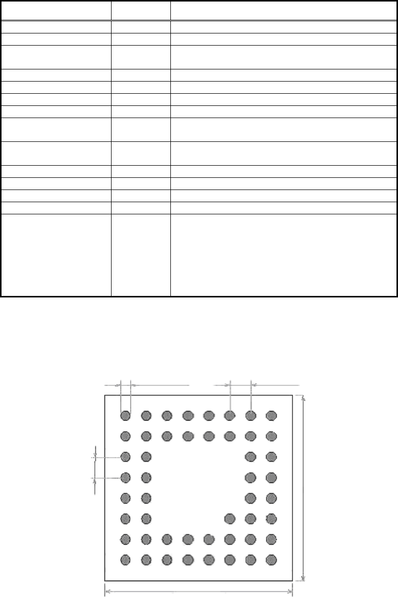
This mode is used when there are places without solder balls on the grid, or the pitches are
different in the horizontal and vertical directions. It is also applicable for BGAs and CSPs in a
zigzag pattern. In this mode, recognition is performed by using the information that specifies
whether there are balls on the grid or not.
Figure 70
Ball diame
ter
Ball pitch
N
Ball pitch E
Body Size Y
Body Size X
93/178
IM-SMT-VSNDIC-0002-000
[Recognition check items]
Items Yes / No Notes
Body Size No
Ball pitch Yes
Table 65
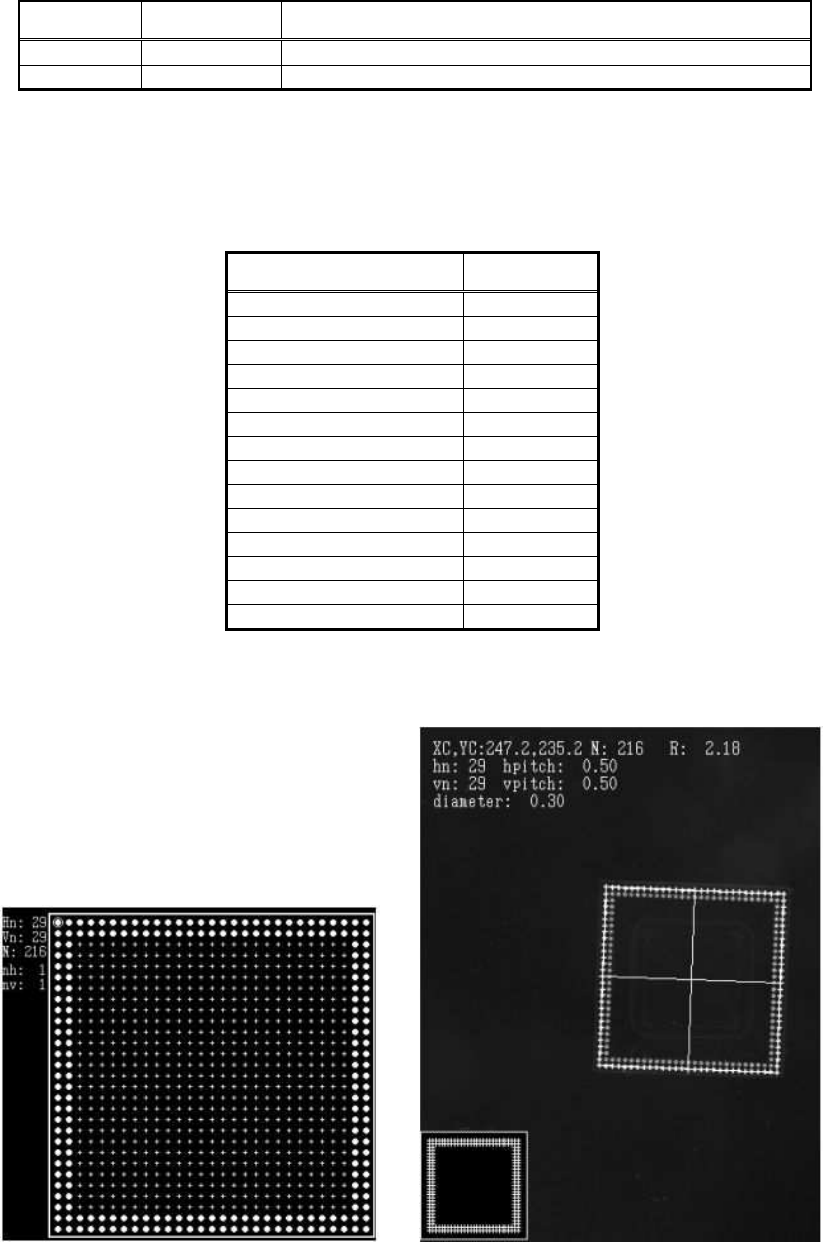
The following is the actual example of the setting and the recognition result.
Recognition is preformed by using the ball recognition file like shown in Figure 71.
<< Items to be ser for BGA>>
Items to be set Set value
Alignment Group Ball
Alignment Type BGA
Comp. Tolerance 30
Search Area (mm) 4.0
Body Size X (mm) 14.0
Body Size Y (mm) 14.0
Body Size Z (mm) 1.0
Ball number N 29
Ball number E 29
BGA diameter (mm) 0.3
BGA Pitch N (mm) 0.5
BGA Pitch E (mm) 0.5
Ball Amount 216
Binary Level 0
Table 66
<< Ball definition file setting state>>
Figure 71 Figure 72
94/178
IM-SMT-VSNDIC-0002-000
2.10.3. Special recognition of BGAs
There are some special recognition algorithms are available in the BGA/CSP recognition
mode.
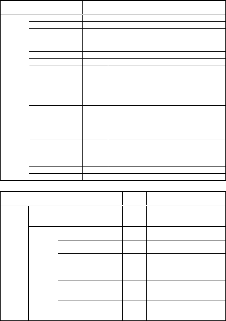
<<Items to be set for Special BGAs>>
Items to be set
Set
value
Explanation
Alignment Group Special
Sets the component category.
Alignment Type Special
Sets the component type.
Comp. Threshold
Comp. Tolerance
Specifies the tolerance of the ball pitch as a
percentage.
Search Area (mm)
Sets the range of the detection.
Body Size X (mm)
Sets the size of the outer edge.
Body Size Y (mm)
Sets the size of the outer edge.
Body Size Z (mm)
Sets the size of the outer edge.
Cntr. Offset X
(mm)
Sets the offset amount in the X direction
from the center position.
Cntr. Offset Y
(mm)
Sets the offset amount in the Y direction
from the center position.
Cntr. Offset R
(mm)
Sets the offset amount of the angle of
rotation.
Ruler Width
Algorithm
Special
1-10
Selects the recognition algorithm when using
a special algorithm.
Base Alignment BGA
Selects the basic component type when
using a special algorithm.
Vision Option 1 Sets option parameter 1.
Vision Option 2 Sets option parameter 2.
Vision Option 3 Sets option parameter 3.
Common
Data
Vision Option 4 Sets option parameter 4.
Items to be set
Set
value
Explanation
Lead Group N 1
Activates the setting of Lead
Group 1N (1).
Common
Ruler Offset N
Lead Number: 1N
Sets the number of rows in
the horizontal direction.
Reflect LL.: 1N (mm)
Sets the total number of
balls.
Lead Width: 1N (mm)
Sets the diameter of the
balls.
Lead Pitch: 1N (mm)
Sets the ball pitch in the
horizontal direction.
Find Pos X: 1N (mm)
Sets the reference position X
of the ball in the horizontal
direction.
N
Direction
Group
1
Find Pos Y: 1N (mm)
Sets the reference position Y
of the ball in the horizontal
direction.