创建组件识别数据的方法.pdf - 第33页
33/178 IM-SMT-VSNDI C-0002 -000 <Component and defined sh apes> W hen the outer shape of the component glo ws, and the r ecognition b y Power T ransistor recognition mode is not stable (See Figure 23 ), the S pecia…
32/178
IM-SMT-VSNDIC-0002-000
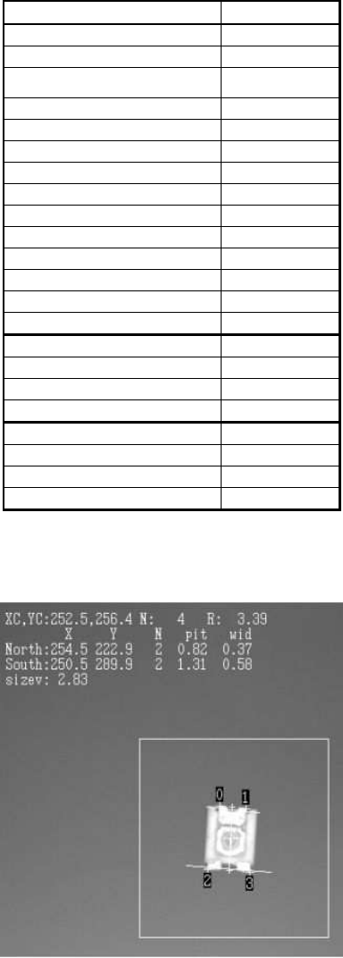
The following is the example in which power transistor recognition was used to recognize
the trimmer capacitor.
<Items to be set for Power Transistor>
Items to be set Set value
Alignment Group IC
Alignment Type P-Tr
Comp. Threshold 50
Comp. Tolerance 30
Search Area (mm) 3.0
Body Size X (mm) 2.2
Body Size Y (mm) 2.9
Body Size Z (mm) 1.0
Cntr. Offset X (mm) 0.0
Cntr. Offset Y (mm) 0.0
Cntr. Offset R (mm) 0.0
Ruler Offset N 2
Ruler Offset S 2
Ruler Width 3
Lead Number: N 2
Reflect LL.: N (mm) 0.3
Lead Width: N (mm) 0.4
Lead Pitch: N (mm) 0.8
Lead Number: S 2
Reflect LL.: S (mm) 0.3
Lead Width: S (mm) 0.6
Lead Pitch: S (mm) 1.4
Table 20
< Recognition Result (P-Tr) >
Figure 22
33/178
IM-SMT-VSNDIC-0002-000
<Component and defined shapes>
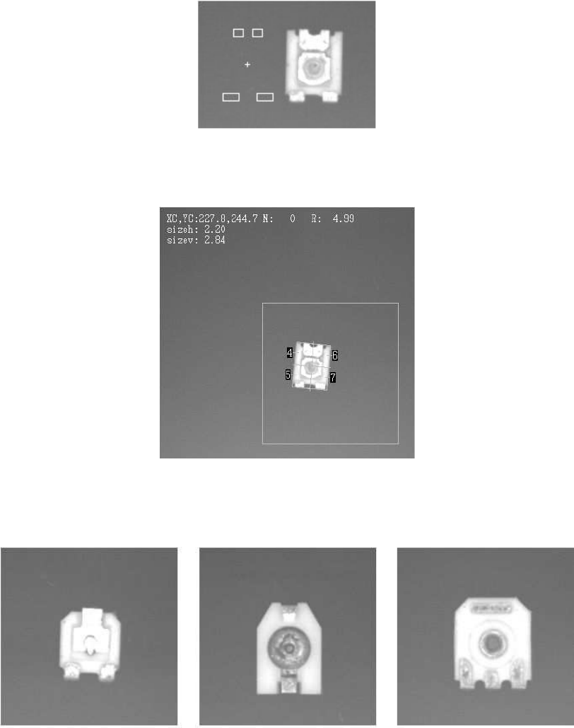
When the outer shape of the component glows, and the recognition by Power Transistor
recognition mode is not stable (See
Figure 23
), the Special Quad. mode may offer more stable
recognition as shown in Figure 24. (Please refer to “2.12.4. Special Quad”.)
Figure 23
<Recognition Result (Sp. Quad)>
Figure 24
The Special Quad. mode offers more stable recognition for trimmer capacitors (See
Figure 25
),
as well. (Please refer to “2.12.4. Special Quad”.)
Figure 25
34/178
IM-SMT-VSNDIC-0002-000
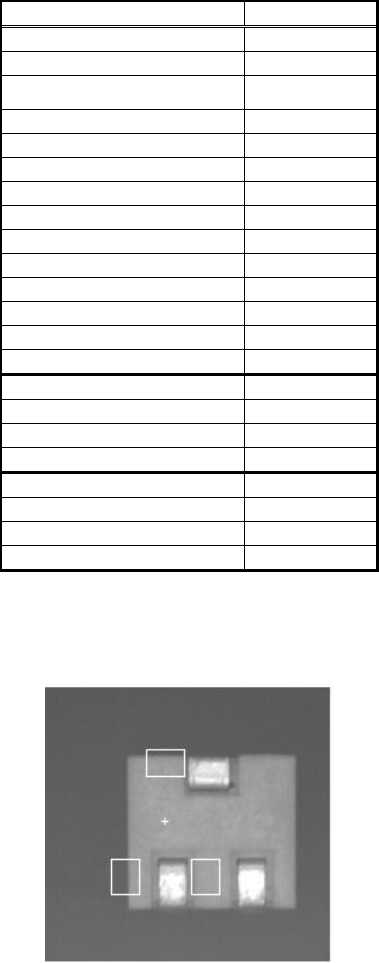
The following shows an example in which the Power Transistor recognition mode is used to
recognize a variable resistor.
Items to be set Set value
Alignment Group IC
Alignment Type P-Tr
Comp. Threshold 40
Comp. Tolerance 30
Search Area (mm) 2.0
Body Size X (mm) 5.0
Body Size Y (mm) 4.2
Body Size Z (mm) 4.0
Cntr. Offset X (mm) 0.0
Cntr. Offset Y (mm) 0.0
Cntr. Offset R (mm) 0.0
Ruler Offset N 5
Ruler Offset S 5
Ruler Width 3
Lead Number: N 1
Reflect LL.: N (mm) 0.8
Lead Width: N (mm) 1.1
Lead Pitch: N (mm) 0.0
Lead Number: S 2
Reflect LL.: S (mm) 1.0
Lead Width: S (mm) 0.8
Lead Pitch: S (mm) 2.3
Table 21
<Component and defined shape>
Figure 26