创建组件识别数据的方法.pdf - 第159页
159/178 IM-SMT-VSNDI C-0002 -000 T able 106 is the exam ple of the directi on determ ination. Figure 129 is the result of the recognition with the data in T able 106. The figure on the left in Figure 129 is the recogniti…
158/178
IM-SMT-VSNDIC-0002-000
In the example of recognition shown in Figure 128, the function that cuts noise inside
the component (See “Appendix 1. Noise processing”.) was used to reduce the effects of the
dark portion at the top.
(A numeric value is set for the component inside noise cut function.)
2.12.4-1. Special recognition of special quad
There are a number of special recognition algorithms available in the Sp Quad
Recognition mode.
(1) Normal: No restriction on the range of value.
(Special components, Special shape, Sp Quad, Normal)
(2) Special 1: Not supported (Lead Width, Lead Pitch check exist)
(3) Special 2: Not supported (hole position check)
(4) Special 3: Check Direction --- The direction is judged based on the brightness of the
specified range (circle). (* This needs to be custom ordered.)
Option 1: Recognition flag
Option 2: Min. Brightness Difference (If the value is 0, 50 is set)
If the difference of the average brightness of the detected circle is less than the
value specified here, it is determined to be an error.
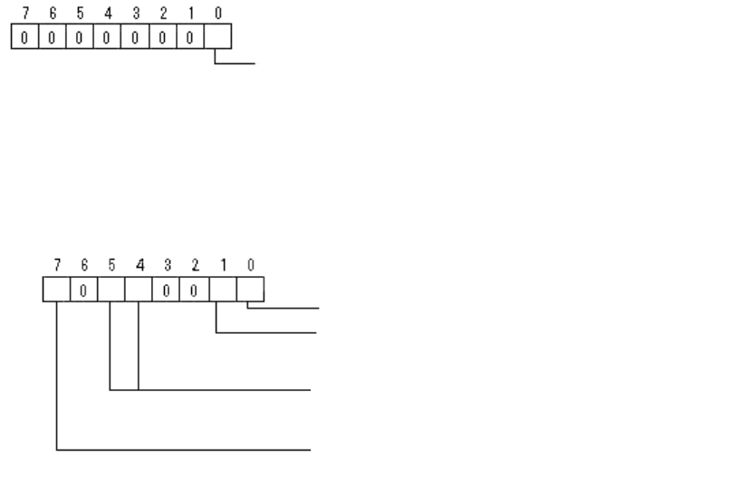
The detection circle is set in the Lead Groups specified by the bit 7,5 and 4 in
Option 1 in order to determine the direction.
- Lead Group: 1 (When set to Lead Group 2, specify 2)
- Lead Number: 0
- Reflect LL: 0
- Lead width: Diameter of detection circle (mm)
- Lead pitch: 0
- Find Pos. X: Detection circle center position X
- Find Pos. Y: Detection circle center position Y
Based on the results of each direction, add +90°, +180° or +270° to the tilt of the
component and set the values.
Bit position
Center Detection Algorithm: (0: Center of Gravity, 1: Apex of Rectangle)
Bit position
Check Type: (0: Black, 1: White)
Direction defined in check data:
0:
North, 1:South, 2:We
st, 3: East
0: (0°, 90°), 1: (0°, 90°, 180°, 270°)
Lead group defined in check data:
0: 1
st
Lead Group is used
1: 2
nd
Lead group is used
159/178
IM-SMT-VSNDIC-0002-000
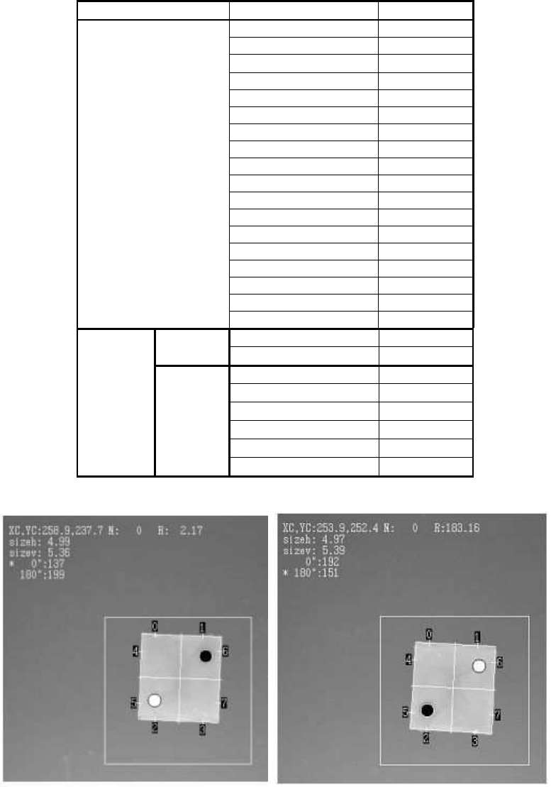
Table 106 is the example of the direction determination.
Figure 129
is the result of the
recognition with the data in Table 106. The figure on the left in
Figure 129
is the
recognition result obtained from the definition. The figure on the right is the recognition
result of the 180 degrees rotated component.
Items to be set Set value
Alignment Group Special
Alignment Type Special
Comp. Threshold 0
Comp. Tolerance 30
Search Area (mm) 4.5
Body Size X (mm) 5
Body Size Y (mm) 5.5
Body Size Z (mm) 1.0
Cntr. Offset X (mm) 0.0
Cntr. Offset Y (mm) 0.0
Cntr. Offset R (mm) 0.0
Ruler Width 1
Algorithm Special 3
Base Alignment Sp Quad
Vision Option 1 0
Vision Option 2 30
Vision Option 3 0
Common
Data
Vision Option 4 0
Lead Group N 1
Common
Ruler Offset N 0
Lead Number: 1N 0
Reflect LL.: 1N (mm)
0.0
Lead Width: 1N (mm)
0.8
Lead Pitch: 1N (mm)
0.0
Find Pos X: 1N (mm)
1.5
N
direction
Group
1
Find Pos Y: 1N (mm)
1.4
Table 106
Figure 129
The circular shapes on the figures in Figure 129 indicate the direction check range, and
160/178
IM-SMT-VSNDIC-0002-000
indicate whether the range was brighter or darker comparing to the rotated check range.
In the example, the value “30” is set to “Vision Option 2”, so the difference in brightness
between the check ranges has to be at least 30.
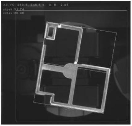
(5) Special 8: Shield recognition
The inclination of the dominant line which forms the contour of the component is
determined to be the inclination of the component.
This is used for the components whose outline of the contour is mainly consisted of the
horizontal or vertical straight lines and the entire contour are connected to each other.
Option 4: “Cut Inner /Outer Noise”, the priority to perform “Cut Inner /Outer Noise” function
and the object type are specified.
Please refer to ”2.12.3-3. Mark 2 Note*3” for details.
Figure 130
(6) Special 10: Check Upside-Down
It identifies whether the surface is the topside or the bottom side by checking the
variation of the brightness of the specified determination range.
Option 1: Threshold of 3-sigma
It sets the threshold of the brightness variation (3-sigma) within the
determination range. Dispersion value becomes larger as the brightness
variation becomes larger.
Option 2: Threshold of Average
It sets the lower limit of the Average brightness value (Ave). It is available
only when “Dispersion” is selected from the “NG condition” and used to
avoid the over determination when performing recognition by the
dispersion value.
Option 3: Judgment Flag
(This function may not be available for some old software versions.)