创建组件识别数据的方法.pdf - 第108页
108/178 IM-SMT-VSNDI C-0002 -000 Items to be set Set value Explanation Comp. Threshold Sets the binarization level. (If 0, the binar ization level is set automaticall y .) Comp. T olerance S pecifies the tolerance as a p…
107/178
IM-SMT-VSNDIC-0002-000
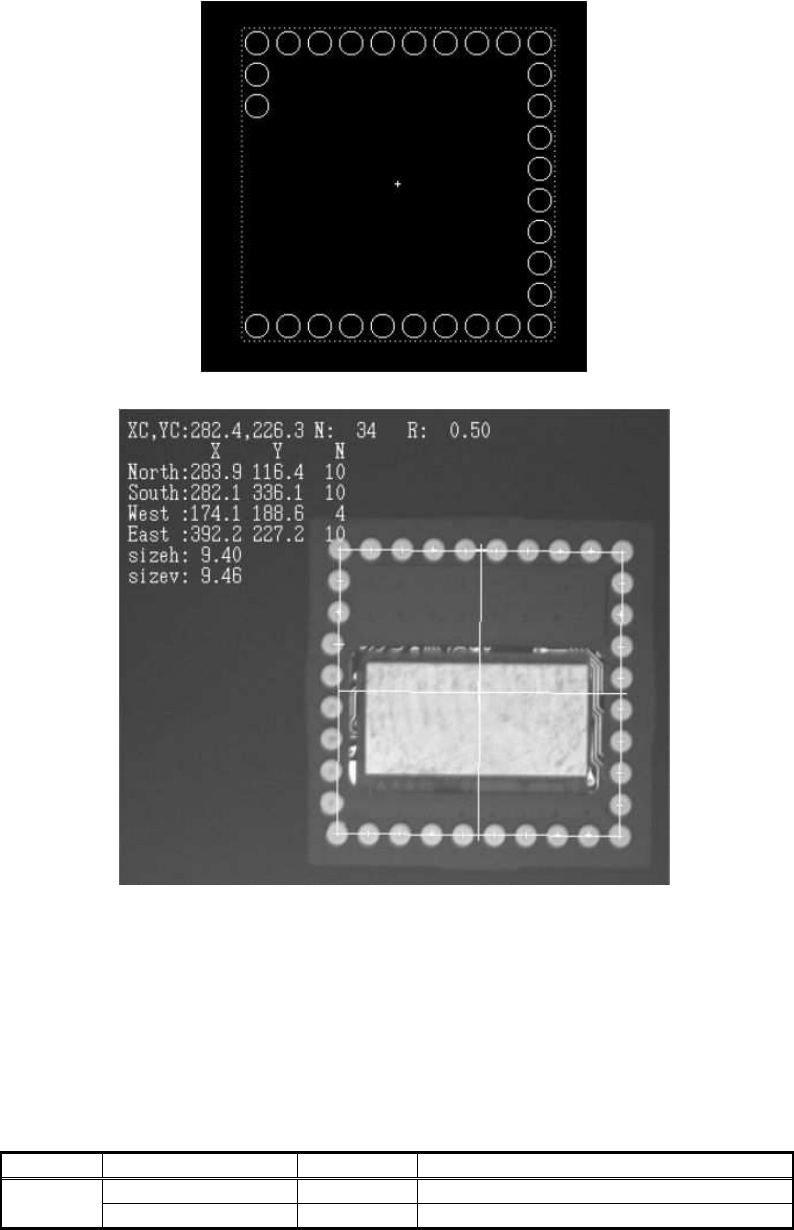
result obtained by the data.
Figure 77
Figure 78
2.10.6 Flip-chip recognition : Special 2 and 3
These recognition modes are used for chips that have the balls placed in a random pattern.
A file containing definitions for each ball position is use for recognition.
With Special 2, the contour tracing based on binarization is used for recognition.
With Special 3, recognition is performed by matching the individual balls.
<< Flip-chip Special 2 &3 >>
Items to be set Set value
Explanation
Alignment Group Special Sets the component category.
Common
Data
Alignment Type Special Sets the component type.

108/178
IM-SMT-VSNDIC-0002-000
Items to be set Set value
Explanation
Comp. Threshold
Sets the binarization level.
(If 0, the binarization level is set
automatically.)
Comp. Tolerance Specifies the tolerance as a percentage.
Search Area (mm) Sets the range of the detection.
Body Size X (mm) Sets the size of the outer edge.
Body Size Y (mm) Sets the size of the outer edge.
Body Size Z (mm) Sets the size of the outer edge.
Cntr. Offset X (mm)
Sets the offset amount in the X direction
from the center position.
Cntr. Offset Y (mm)
Sets the offset amount in the Y direction
from the center position.
Cntr. Offset R (mm)
Sets the offset amount of the angle of
rotation.
Ruler Width 0
Algorithm Special 2/3
Selects the recognition algorithm when
using a special algorithm.
Base Alignment Flip chip
Selects the basic component type when
using a special algorithm.
Vision Option 1 0
An index of the ball position definition
file.
Vision Option 2 0
Ball matching level (%)
(This is effective only for Special 3
algorithm.)
Vision Option 3 0
Vision Option 4
*Note 1
Specifies the noise cut for inside and
outside of the component, the order of
execution and the object type.
(This is effective only for Special 2
algorithm.)
Table 74
Note *1: . This option parameter consists of one byte of data, and each bit has different
meaning (Please refer to “2.12.3-3. Mark 2, Note *3” for the details.)
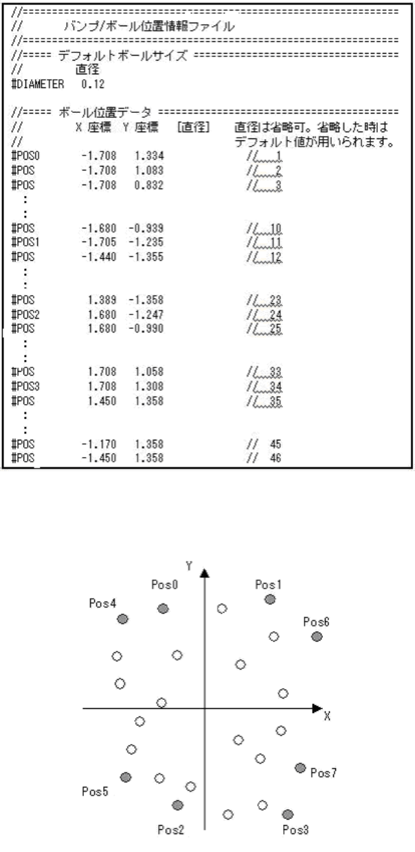
As shown in Figure 79, the definitions for the individual ball positions are stored in a ball
position definition file (text file) (Lines beginning with // are comments.)
109/178
IM-SMT-VSNDIC-0002-000
Figure 79
The following is the definition coordinate.
Figure 80
Pos 0 ~ 7 are the balls referred to as reference balls, and are used for rough position