创建组件识别数据的方法.pdf - 第73页
73/178 IM-SMT-VSNDI C-0002 -000 The following is the actual example of the s etting and the recognitio n result. As the tilt is not stable just by recogn izing the E dir ection, the f ixed leads are a lso targeted for re…
72/178
IM-SMT-VSNDIC-0002-000
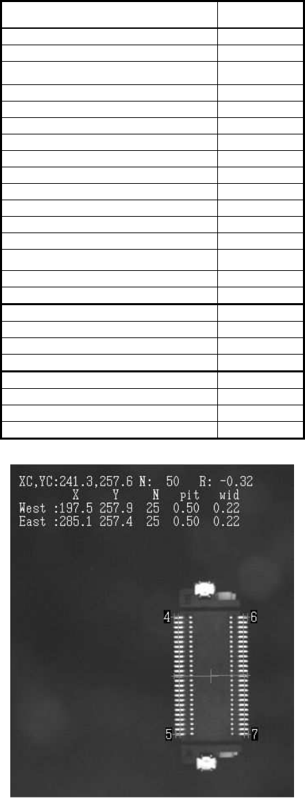
The following is the actual example of the setting and the recognition result.
<< Items to be set for 2-direction connectors>>
Items to be set Set value
Alignment Group Connector
Alignment Type Con-NSEW
Comp. Threshold 50
Comp. Tolerance 30
Search Area (mm) 4.0
Body Size X (mm) 8.0
Body Size Y (mm) 14.0
Body Size Z (mm) 7.0
Cntr. Offset X (mm) 0.0
Cntr. Offset Y (mm) 0.0
Cntr. Offset R (mm) 0.0
Ruler Offset N 0
Ruler Offset S 0
Ruler Offset E 5
Ruler Offset W 5
Ruler Width 3
Lead Number E 25
Lead Pitch E (mm) 0.5
Lead Width E (mm) 0.2
Reflect LL. E (mm) 0.8
Lead Number W 25
Lead Pitch W (mm) 0.5
Lead Width W (mm) 0.2
Reflect LL. W (mm) 0.8
Table 49
Figure 56

73/178
IM-SMT-VSNDIC-0002-000
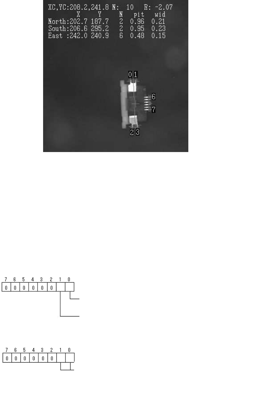
The following is the actual example of the setting and the recognition result. As the tilt is not
stable just by recognizing the E direction, the fixed leads are also targeted for recognition.
<< Items to be set for 3-direction connectors>>
Items to be set Set value
Alignment Group Connector
Alignment Type Con-NSEW
Comp. Threshold 50
Comp. Tolerance 30
Search Area (mm) 4.0
Body Size X (mm) 5.5
Body Size Y (mm) 10.0
Body Size Z (mm) 1.0
Cntr. Offset X (mm) 0.0
Cntr. Offset Y (mm) 0.0
Cntr. Offset R (mm) 0.0
Ruler Offset N 3
Ruler Offset S 3
Ruler Offset E 3
Ruler Offset W 0
Ruler Width 3
Lead Number N 2
Lead Pitch N (mm) 1.0
Lead Width N (mm) 0.2
Reflect LL. N (mm) 0.5
Lead Number S 2
Lead Pitch S (mm) 1.0
Lead Width S (mm) 0.2
Reflect LL. S (mm) 0.5
Lead Number E 6
Lead Pitch E (mm) 0.5
Lead Width E (mm) 0.2
Reflect LL. E (mm) 0.8
Table 50
74/178
IM-SMT-VSNDIC-0002-000
Figure 57
2.9.3. Special recognition of connectors
There are several algorithms available in the Connector Recognition mode.
(1) Special 1: Side Lead Fitting
This mode is effective when there are items other than leads that show up as white,
which makes it difficult to detect the leads easily.
This mode improves the recognition rate by checking the positional relations between the
leads and extracting the combination best fits the component definition when detecting
the end leads.
Option 1: Lead detection flag.
Option 2: Filter settings
Bit position
Detection of check of distance between 2 pins at lead search end:
( 0:Yes, 1:No)
Lead search direction: ( 0: Inclined 1: Horizontal / vertical)
Bit position
Number of times that filter is applied when lead search is conducted.
(0-3) The lead search should be performed by using the filter with its
maximum value in order to respond to the components whose lead is
curved, and the curved surface is the ground plane to the board.
( 0: No filtering, 1: 3 x 3 maximum filter, 2: 5 x 5 maximum filter,
3: 7 x 7 maximum filter)