创建组件识别数据的方法.pdf - 第96页
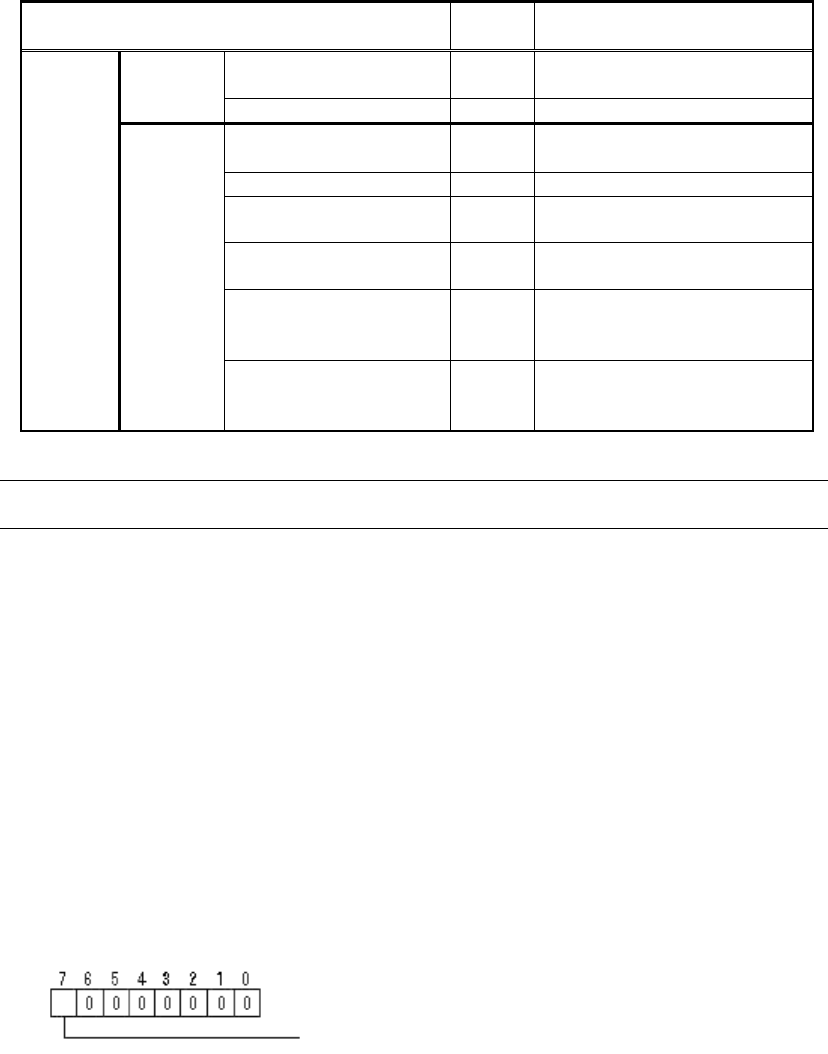
96/178 IM-SMT-VSNDI C-0002 -000 << Items to be set for Special BG A>> Items to be set Set value Alignment Group S pecial Alignment T ype S pec ial Comp. Threshold 0 Comp. T olerance 30 Search Are a (mm) 4.0 B…
95/178
IM-SMT-VSNDIC-0002-000
Items to be set
Set
value
Explanation
Lead Group E 1
Activates the setting of Lead
Group 1E (1).
Common
Ruler Offset E
Lead Number: 1E
Sets the number of rows in
the vertical direction.
Reflect LL.: 1E (mm)
Lead Width: 1E (mm)
Sets the diameter of the
balls.
Lead Pitch: 1E (mm)
Sets the ball pitch in the
vertical direction.
Find Pos X: 1E (mm)
Sets the reference position X
of the ball in the vertical
direction.
E
Direction
Group
1
Find Pos Y: 1E (mm)
Sets the reference position Y
of the ball in the vertical
direction.
Table 67
Note:
The parameters other than those shown in Table 67 are not used, and should be set to 0.
(1) Special 1: Polarity judgment function
This function is used in the Simple BGA Recognition mode to judge polarity
based on whether the specified ball exists or not.
Option 1: Column number of the ball for polarity judgment in the horizontal direction.
Option 2: Row number of the ball for polarity judgment in the vertical direction.
Option 3: Polarity Ball: (0:None, 1:Exist)
(2) Special 2: The Standard BGA Recognition mode runs in this mode.
Option 1: Lower 8 bits of the index number for the ball position information
Option 4: Upper 8 bits of the index number for the ball position information
Option 2: Binarization correction parameter
Option 3: Recognition flag
(3) Special 3: Simple recognition of ceramic BGAs
This is used for recognition of the BGAs whose base is made of white ceramic.
The ball position definition information is not used.
Option 2: Ball Exist Threshold Level
The following is the actual example of the recognition.
Bit position
Excessive Ball check: (0: None, 1:Exist)
96/178
IM-SMT-VSNDIC-0002-000
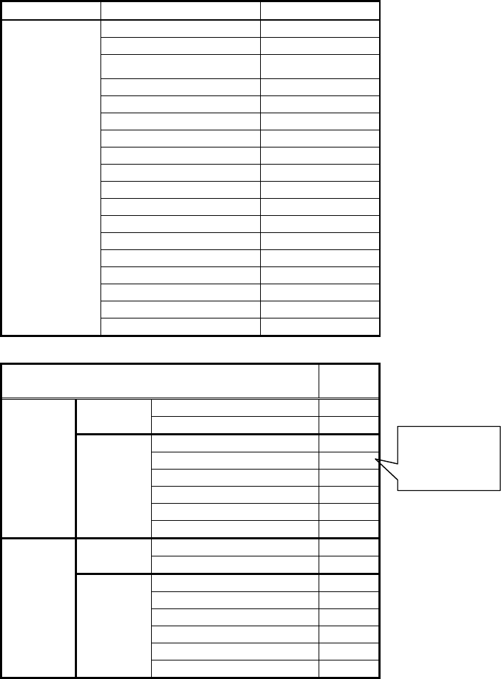
<< Items to be set for Special BGA>>
Items to be set Set value
Alignment Group Special
Alignment Type Special
Comp. Threshold 0
Comp. Tolerance 30
Search Area (mm) 4.0
Body Size X (mm) 55.0
Body Size Y (mm) 15.0
Body Size Z (mm) 7.0
Cntr. Offset X (mm) 0.0
Cntr. Offset Y (mm) 0.0
Cntr. Offset R (mm) 0.0
Ruler Width 3
Algorithm Special 3
Base Alignment BGA
Vision Option 1 0
Vision Option 2 0
Vision Option 3 0
Common
Data
Vision Option 4 0
Items to be set
Set
value
Lead Group N 1
Common
Ruler Offset N 0
Lead Number: 1N 40
Reflect LL.: 1N (mm) 400.0
Lead Width: 1N (mm) 0.8
Lead Pitch: 1N (mm) 1.27
Find Pos X: 1N (mm) -24.77
N
Direction
Group
1
Find Pos Y: 1N (mm) 5.72
Lead Group E 1
Common
Ruler Offset E 0
Lead Number: 1E 10
Reflect LL.: 1E (mm) 0
Lead Width: 1E (mm) 0.8
Lead Pitch: 1E (mm) 1.27
Find Pos X: 1E (mm) 24.77
E
Direction
Group
1
Find Pos Y: 1E (mm) 5.72
Table 68
Set the total
number of
balls.
97/178
IM-SMT-VSNDIC-0002-000
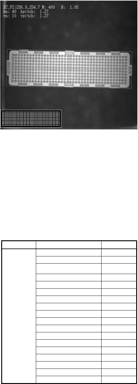
Figure 73
(4) Special 4: Recognition of ceramic BGAs (Using the ball position information)
This is used for recognition of the BGAs whose base is made of white ceramic.
The ball position definition information is used.
Option 1: Lower 8 bits of the index number for the ball position information
Option 4: Upper 8 bits of the index number for the ball position information
Option 2: Threshold value for judging whether the balls exist or not
The following is the actual example of recognition.
<< Items to be set for Special BGA>>
Items to be set Set value
Alignment Group Special
Alignment Type Special
Comp. Threshold 0
Comp. Tolerance 30
Search Area (mm) 4.0
Body Size X (mm) 32.0
Body Size Y (mm) 32.0
Body Size Z (mm) 3.0
Cntr. Offset X (mm) 0.0
Cntr. Offset Y (mm) 0.0
Cntr. Offset R (mm) 0.0
Ruler Width 3
Algorithm Special 4
Base Alignment BGA
Vision Option xx
Vision Option 2 0
Vision Option 3 0
Common
Data
Vision Option 4 xx