创建组件识别数据的方法.pdf - 第166页
166/178 IM-SMT-VSNDI C-0002 -000 The recognition results are detecte d at the sub-p ixel level. The following sh apes can b e selected as t he mark shape: - Circle - Square/ Ob long - T r ue triangle - S pecial sh ape Th…
165/178
IM-SMT-VSNDIC-0002-000
The circular shapes on the figures in
Figure 133
indicate the direction check range, and
indicate whether the range was brighter or darker comparing to the rotated check range.
In the example, the value “0” is set to “Vision Option2”, so the difference in brightness
between the check range has to be at least 50.
3. Fiducial Mark Recognition
There are several methods that can be used for fiducial mark recognition. These can be
selected from those noted in Table 111 based on the values specified for the recognition
type and shape type.
Circle
Square/
Rectangle
Triangle
Sp.Shape
Corner TopEdge
CirEdge*
Normal
Center of
gravity
detection
Center of
gravity
detection
Center of
gravity
detection
Center of
gravity
detection
Corner
detection
Tip
detection
Contour
circle
detection
Special 1
Contour
circle
detection
Contour
square
Contour
triangle
Center of
gravity
detection
Corner
detection
Tip
detection
Contour
circle
detection
Special 2
Edge
circle
detection
Edge
square
Edge
triangle
Center of
gravity
detection
Corner
detection
Tip
detection
Edge
circle
detection
PTRN
Outline
Matching
1
Matching
1
Matching
1
Matching
1
Matching
1
Matching
1
Matching
1
PTRN
GrayLev
Matching
2
Matching
2
Matching
2
Matching
2
Matching
2
Matching
2
Matching
2
PTRN*
Whole
Matching
3
Matching
3
Matching
3
Matching
3
Matching
3
Matching
3
Matching
3
Table 111
Note*:
“Cir Edge” and “PTRN Whole” may not be available for some machine series and software
versions.
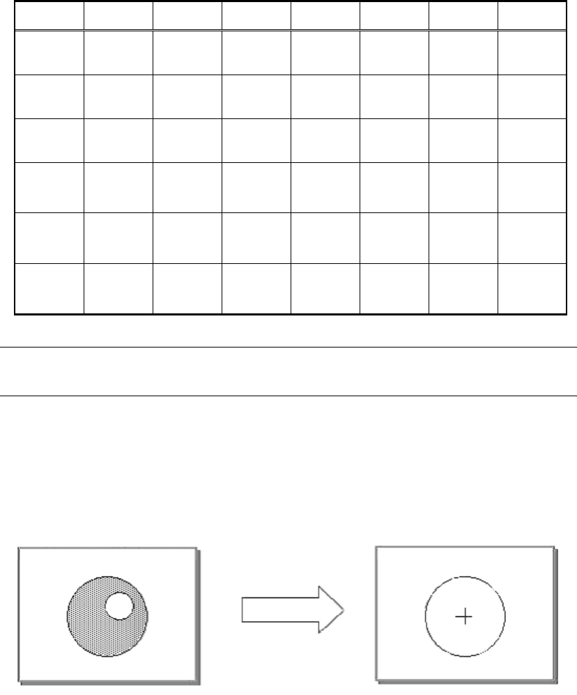
3.1. Center of Gravity detection (Recognition type: Normal)
The mark contour is determined, and then the center of the mark is determined from the
center of gravity position of the contour. If there is a projection or a dent, it affects the
detection position. However, the “hole” inside the contour does not affect the recognition
result.
Figure 134
The contour is
detected.
166/178
IM-SMT-VSNDIC-0002-000
The recognition results are detected at the sub-pixel level.
The following shapes can be selected as the mark shape:
- Circle
- Square/ Oblong
- True triangle
- Special shape
The surface area and shape constant are checked for each of these shapes.
(Shape constant of the “Special shape” and “Oblong” are not checked. Only the surface area
is checked for the shapes.)
This recognition method is suitable for objects with brightness contrast.
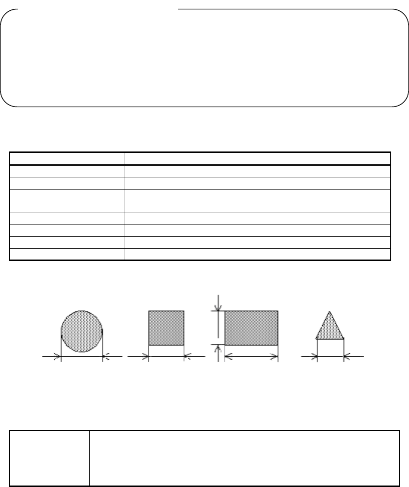
<< Items to be set for center of gravity detection >>
Shape Type Selects from circle/square/triangle/special shape.
Surface type Selects reflecting/non-reflecting
Algorithm Type Normal
Mark Threshold Sets the binarization level. (If this is set to 0, the
binarization level is set automatically.)
Tolerance Sets the shape tolerance.
Search Area Sets the detection range.
Cut Inner Noise Selects from 0 through 9.
Cut Outer Noise Selects from 0 through 9.
Table 112
Figure 135
<< For circle / (square /rectangle)/ true triangle >>
Mark OutSize
Sets the Body Size.
(As shown in Figure 135, set the diameter for circle, the length of the
side for square and triangle, and for oblong, set the length of the
bottom line for X, height for Y.)
Table 113
The value obtained from the formula ( The perimeter
2
/ The surface area) is set as a
constant value, like those shown below. This is referred to as “shape constant”.
Circle: Perimeter
2
divided by surface area = 4π
Square: Perimeter
2
divided by surface area = 16
True triangle: Perimeter
2
divided by surface area = 36 / √ 3
[ What is
“
Shape constant
”
? ]
167/178
IM-SMT-VSNDIC-0002-000
<<For special shape>
Mark Outsize X (mm) Sets the Body Size X.
Mark Outsize Y (mm) Sets the Body Size Y.
Area (mm
2
) Sets the area.
Outline Sets the perimeter
Table 114
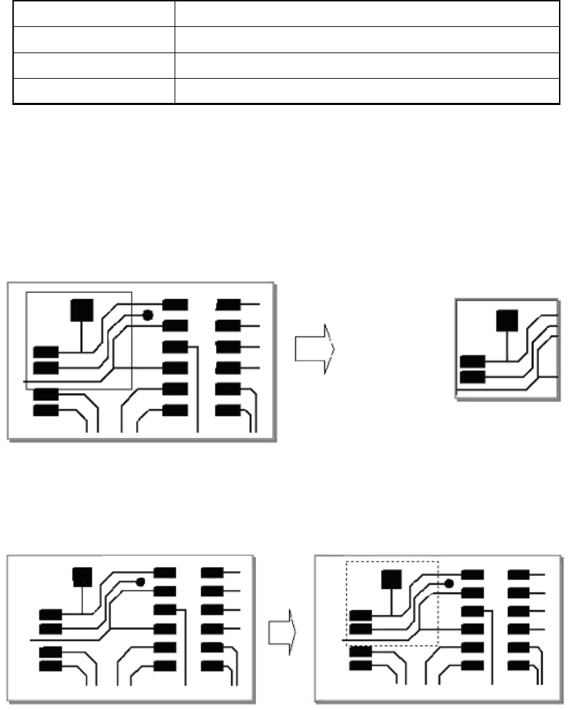
3.2. Template matching (Recognition type: pattern)
In this method, a mark that has been registered in advance is used to detect the mark that is
the closest to the registered mark from among those on the image that has been captured.
A template is created from the specified field.
Figure 136
Matching is performed on the captured image by using the registered template.
Figure 137
The position that matches most closely to the registered mark is detected.
The recognition results are detected at the sub-pixel level.
In “PTRN Outline” mode, recognition is performed by registering the contour part of the
fiducial mark as a template.
In “PTRN Graylev” mode, the straight line on each vertical and horizontal direction are set in
order to speed up the detection, and the rough position is determined by using the brightness
Template registration
Matching