创建组件识别数据的方法.pdf - 第54页
54/178 IM-SMT-VSNDI C-0002 -000 Items to be set Set value Explanation Body Size Y (mm) Sets the si ze of the outer e dge. Body Size Z (mm ) Sets the size of the outer edge. Ruler Offset Set s the offs et amount for the d…

53/178
IM-SMT-VSNDIC-0002-000
Lead Group E 1
Specifies the number for the
Lead Group in the E direction.
(1)
Common
Ruler Offset E
Sets the offset amount of the
detection line in the E
direction.
Lead Number: 1E
Sets the number of lead in the
E direction.
Reflect LL.: 1E (mm)
Sets the lead length on the
image in the E direction.
Lead Width: 1E (mm)
Sets the width of the lead in
the E direction.
Lead Pitch: 1E (mm)
Sets the pitch in the E
direction.
Find Pos X: 1E (mm)
Sets the reference position X
in the E direction.
E
Direction
Group 1
Find Pos Y: 1E (mm)
Sets the reference position Y
in the E direction.
Lead Group W 1
Specifies the number for the
Lead Group in the W
direction. (1)
Common
Ruler Offset W
Sets the offset amount of the
detection line in the W
direction.
Lead Number: 1W
Sets the number of leads in
the W direction.
Reflect LL.: 1W (mm)
Sets the lead length on the
image in the W direction.
Lead Width: 1W (mm)
Sets the width of the lead in
the W direction.
Lead Pitch: 1W (mm)
Sets the pitch in the W
direction.
Find Pos X: 1W (mm)
Sets the reference position X
in the W direction.
W
Direction
Group 1
Find Pos Y: 1W (mm)
Sets the reference position Y
in the W direction.
Table 34
Note:
The parameters other than those shown in
Table 34
are not used, and should be set to 0.
2.7. PLCCs
<Items to be set for PLCCs>
Items to be set Set value
Explanation
Alignment Group IC Sets the component category.
Alignment Type PLCC Sets the component type.
Comp. Threshold
Sets the detection level difference for lead
detection.
(See “Appendix 2. Detection level
differences used to detect leads (threshold value)”.)
Comp. Tolerance
Specifies the tolerance of the lead pitch as a
percentage.
Search Area (mm) Sets the range of the detection.
Body Size X (mm) Sets the size of the outer edge.
54/178
IM-SMT-VSNDIC-0002-000
Items to be set Set value
Explanation
Body Size Y (mm) Sets the size of the outer edge.
Body Size Z (mm) Sets the size of the outer edge.
Ruler Offset Sets the offset amount for the detection line.
Ruler Width
Lead Number N
Sets the number of leads in the cross direction.
Lead Number E
Sets the number of leads in the lengthwise
direction.
Reflect LL. (mm)
Sets the lead length on the image.
Lead Width (mm)
Sets the width of the lead.
Lead Pitch (mm)
Sets the pitch.
Table 35
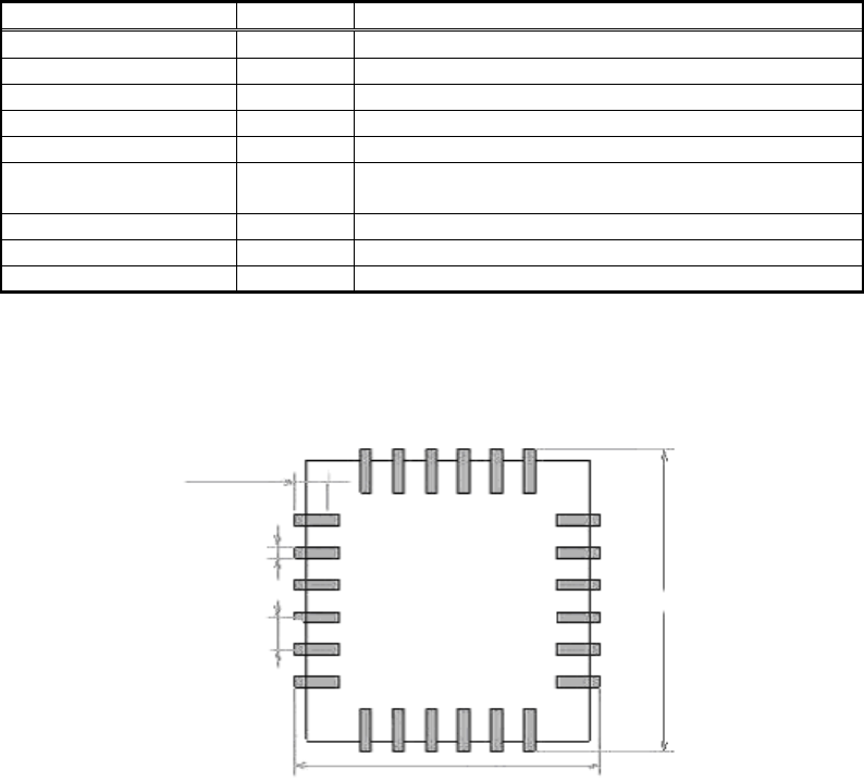
In the normal mode, the recognition method is the same as QFP recognition.
Figure 46
QFPs and PLCCs are similar in terms of shape. However, unlike QFPs, the lead tips of
PLCCs may not be stably recognized (because the shape of the leads are not planar).
Also, in some cases, all of the illumination sources (Main light, Coaxal light and Side light)
need to be turned on in order to light up the leads stably. In this case, “Yes” should be
selected from the “All Lighting On” recognition parameter.
If the recognition is still not stable, Lead root recognition mode should be used.
In this mode, the root of the lead is recognized not the tip.
In order to improve the recognition rate, the positional relations between the leads are
checked and the combination best fits the component definition is extracted when the end
leads are detected
When this recognition mode is selected, either “Inside Recognition” or “Inside +
LeadAutoSearch” should be selected for ”Recognition Way” in the recognition parameters.
In the “LeadAutoSearch” mode, Lead detection is performed by using the lead pitch/ lead
width parameter and extracting the data best fits the definition data when detecting the lead
row.
Lead length
Lead width
Pitch
Body Size Y
Body Size X
55/178
IM-SMT-VSNDIC-0002-000
[Recognition check items]
Items Yes / No Notes
Body Size No
Lead pitch Yes
The pitch in the direction with one lead is not checked.
Lead width May exist
Checks only when the lead width is more than 1.0mm.
(Note 1)
Reflect LL No
Find Pos No
Table 36
Note:
“Lead width” check function may not be available for the old softwares.
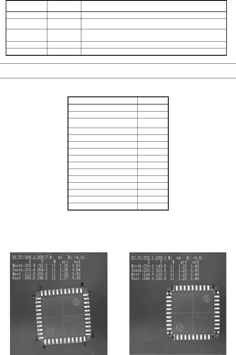
The following is the actual example of the recognition of the normal lead tip detection and root
detection.
Items to be set Set value
Alignment Group IC
Alignment Type PLCC
Comp. Threshold 50
Comp. Tolerance 15
Search Area (mm) 6.0
Body Size X (mm) 17.53
Body Size Y (mm) 17.53
Body Size Z (mm) 4.30
Ruler Offset 5
Ruler Width 3
Lead Number N 11
Lead Number E 11
Reflect LL. (mm) 1.4
Lead Width (mm) 0.43
Lead Pitch (mm) 1.27
Table 37
When performing root recognition, it may not be able to be detected without inputting the
correct Lead length. Please check the display of the defined shape to make sure it matches to
the actual component.
<Lead tip detection> <Lead root detection>
Figure 47