创建组件识别数据的方法.pdf - 第42页
42/178 IM-SMT-VSNDI C-0002 -000 (This s pecifies to use “degrees ” as a unit, an d when th e value is 0, the c heck is perform ed as “ 5 degrees” has been spec ified.) An error occ urs if the sum of the bending ang les d…
41/178
IM-SMT-VSNDIC-0002-000
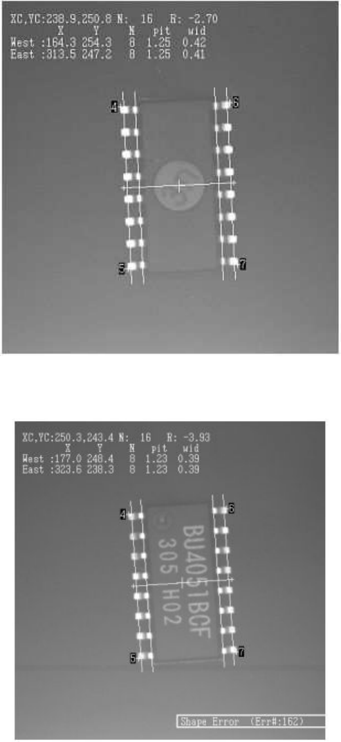
<When the component is correctly positioned >
Figure 32
<When a reversed component is detected>
Figure 33
6) Special 6: Check the bending of the whole leads of SOP components
This mode checks to see if all of the leads of an SOP are bent between the tips
and the roots of the leads. The recognition mode is the same as that of Special
1.
Option 1: Bending angle tolerance value
42/178
IM-SMT-VSNDIC-0002-000
(This specifies to use “degrees” as a unit, and when the value is 0, the check is
performed as “ 5 degrees” has been specified.)
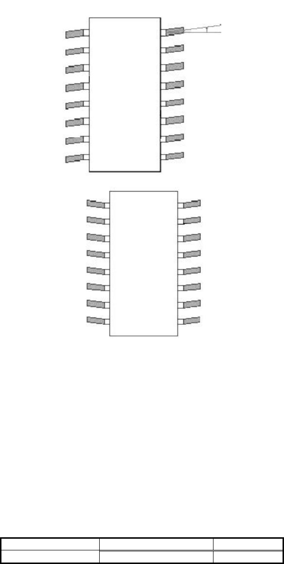
An error occurs if the sum of the bending angles detected on the left and right
sides is larger than the value specified with Option 1. If the leads on the left and
right are bent in different directions as shown in
Figure 34
, an error occurs. If the
leads are bent in the same direction, as shown in
Figure 35
, no error occurs.
Figure 34
Figure 35
Set the detection line at the tip of the leads and at the root of the leads, and obtain the center
of these two lines. The tilt of the whole leads is detected based on these values. Detect the tilt
of the lead on both left and right side, then add these results.
The tip line is set to the inside of the Ruler Offset by the amount of the distance from the
lead tip to the Ruler Offset. The root line is set to the inside of the Ruler Offset by the amount
of the distance from the lead tip to the point equal to the value where the detection line offset
is subtracted from the lead length. For this reason, the length including the lead root portions
is set as Reflect LL unlike the usual case of setting.
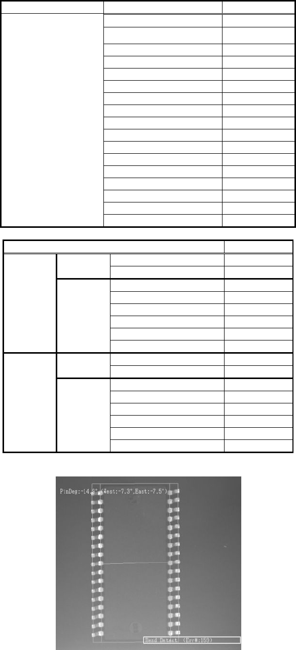
Figure 36 shows the example of the bent lead check. An error has occurred due to the bent
leads. The lead length is set longer than the normal value in order to set the inside detection
line.
<Items to be set for SOP Special mode>
Items to be set Set value
Common Alignment Group Special
Bent angle of the lead
43/178
IM-SMT-VSNDIC-0002-000
Items to be set Set value
Alignment Type Special
Comp. Threshold
Comp. Tolerance
Search Area (mm)
Body Size X (mm)
Body Size Y (mm)
Body Size Z (mm)
Cntr. Offset X (mm)
Cntr. Offset Y (mm)
Cntr. Offset R (mm)
Ruler Width
Algorithm Special 6
Base Alignment SOP
Vision Option 1 5
Vision Option 2 0
Vision Option 3 0
Data
Vision Option 4 0
Items to be set Set value
Lead Group E 1
Common
Ruler Offset E 3
Lead Number: 1E 17
Reflect LL.: 1E (mm) 1.2
Lead Width: 1E (mm) 0.4
Lead Pitch: 1E (mm) 1.0
Find Pos X: 1E (mm) 5.1
E
Direction
Group
1
Find Pos Y: 1E (mm) 8.0
Lead Group W 1
Common
Ruler Offset W 3
Lead Number: 1W 17
Reflect LL.: 1W (mm) 1.2
Lead Width: 1W (mm) 0.4
Lead Pitch: 1W (mm) 1.0
Find Pos X: 1W (mm) -5.1
W
Direction
Group
1
Find Pos Y: 1W (mm) 8.0
Table 27
Figure 36