创建组件识别数据的方法.pdf - 第4页
4/178 IM-SMT-VSNDI C-0002 -000 Appendix ........................................................................... ......................................... ......... 173 Appendix 1. No ise proces sing .................…
3/178
IM-SMT-VSNDIC-0002-000
2.11.2 MELF chips..................................................................................................... 114
2.11.3 Bare chip.......................................................................................................... 115
2.11.5 Special chips.................................................................................................... 117
2.11.6 Small Chip ....................................................................................................... 118
2.11.6 Special recognition of chip components .......................................................... 119
(standard chips, MELF chips, special chips)................................................................. 119
2.11.7 Special Recognition of chip components (Cylindrical chips) ........................... 124
2.12 Special components............................................................................................... 124
2.12.1 Special shapes ................................................................................................ 124
2.12.2 Odd-shape chips ............................................................................................. 128
2.12.3 Mark types ....................................................................................................... 129
2.12.4 Special Quad ................................................................................................... 155
2.12.5 Center of Gravity detection.............................................................................. 162
3. Fiducial Mark Recognition...................................................................................... 165
3.1 Center of Gravity detection (Recognition type: Normal) .......................................... 165
3.2 Template matching (Recognition type: pattern) ....................................................... 167
3.3 Corner detection....................................................................................................... 168
3.4 Top Edge detection .................................................................................................. 169
3.5 CirEdge detection..................................................................................................... 170
3.6 Contour rectangle detection / contour triangle detection ......................................... 170
3.7 Edge circle detection................................................................................................ 171
3.8 Edge rectangle / triangle detection .......................................................................... 171
4/178
IM-SMT-VSNDIC-0002-000
Appendix ............................................................................................................................. 173
Appendix 1. Noise processing.......................................................................................... 173
Appendix 2. Detection level differences used to detect leads (threshold value) ........ 174
Appendix 3. Creating simple data in the special recognition modes ........................... 175
Appendix 4. Lead position check ..................................................................................... 176
Appendix 5. Reading and interpreting the recognition results display........................ 177
5/178
IM-SMT-VSNDIC-0002-000
1. Component data
In vision recognition, data pertaining to the shape of the component, the image input condition
and other elements are required in order to perform component recognition.
This is hereafter referred to as “component data”.
The section below shows the configuration of the component data.
1.1 Component data configuration
Component data consists of the following two parts:
- Shape parameter
- Vision parameter
The vision parameters are the parameters that are required in order for component
recognition to actually be carried out, such as the lighting level and threshold value.
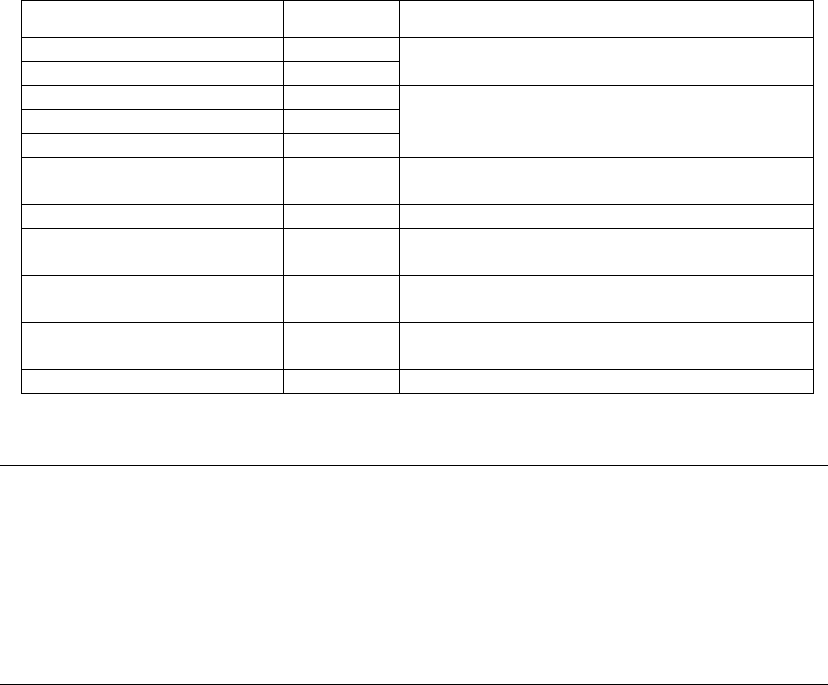
<Examples of recognition parameters>
Items to be set Set value
Notes
Alignment Module Back
Alignment Module Fore
Specifies the device that can be used for
recognition.
Light Main
Light Coax
Light Side
Selects the type of illumination to be used.
Lighting Level
Sets the brightness of the illumination to one
of nine levels from 0/8 through 8/8.
Comp. Threshold Sets the threshold value for recognition.
Comp. Tolerance Sets the tolerance check value as a
percentage.
Search Area(mm) Sets a range for carrying out a component
search.
Datum Angle (degree) Selects from “Normal”,”90 degrees”, “180
degrees” or “270 degrees”.
Multi MACS
Specifies whether to use Multi MACS or not.
Table 1
Caution:
The parameter “Datum Angle” is used when the actual angle of the component supplied from
the feeder is different from the angle specified by the component definition.
Though “Normal” is usually selected for this parameter, in the aforementioned case, “90
degrees”, “180 degrees” or “270 degrees” is specified depends which angle the component is
recognized.
This allows components to be recognized using the standard component data, without
correcting the existing data. (This is a system that automatically rotates the component data
for recognition based on this specification in the image recognition system.