创建组件识别数据的方法.pdf - 第163页
163/178 IM-SMT-VSNDI C-0002 -000 Figure 132 2.12.5-1. Special recog nition o f the Center of G ravity detectio n (1) Special 1: Not suppor ted (Chec k of the average brightness within the obj ects) (2) Special 2: Not sup…
162/178
IM-SMT-VSNDIC-0002-000
2.12.5. Center of Gravity detection
In this mode, the component contour is determined, and then recognition is performed on the
component by using the center of gravity position and the tilt of the axis of the contour.
This method is used to recognize irregular shaped components. However, the tilt of the
square and circular components is not defined, as they have no axes.
<< Items to be set for Center of Gravity detection >>
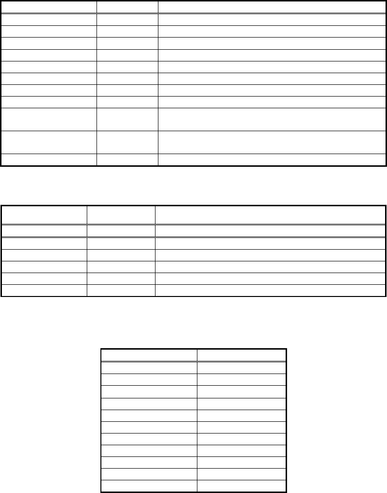
Items to be set Set value Explanation
Alignment Group Special Sets the component category.
Alignment Type Gravity Sets the component type.
Comp. Threshold Sets the binarization level.
Comp. Tolerance Specifies the shape tolerance as a percentage.
Search Area (mm) Sets the range of the detection.
Body Size X (mm) Sets the size of the outer edge.
Body Size Y (mm) Sets the size of the outer edge.
Body Size Z (mm) Sets the size of the outer edge.
Cntr. Offset X (mm)
Sets the offset amount in the X direction from the
center position.
Cntr. Offset Y (mm)
Sets the offset amount in the Y direction from the
center position.
Cntr. Offset R (mm)
Sets the offset amount of the angle of rotation.
Table 107
[Recognition check items]
Items Yes / No Notes
Surface Area Yes Checks the surface area of the targeted item
Body Size No
Lead pitch No
Lead width No
Lead length No
Lead position No
Table 108
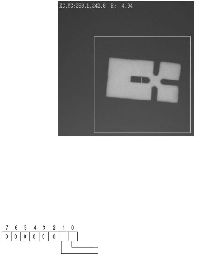
The following is the example of the recognition of Center of Gravity detection.
Items to be set Set value
Alignment Group Special
Alignment Type Gravity
Comp. Threshold 0
Comp. Tolerance 30
Search Area (mm) 6.0
Body Size X (mm) 9.0
Body Size Y (mm) 5.0
Body Size Z (mm) 22.0
Cntr. Offset X (mm)
0.0
Cntr. Offset Y (mm)
0.0
Cntr. Offset R (mm)
0.0
Table 109
163/178
IM-SMT-VSNDIC-0002-000
Figure 132
2.12.5-1. Special recognition of the Center of Gravity detection
(1) Special 1: Not supported (Check of the average brightness within the objects)
(2) Special 2: Not supported (Check of the average brightness within the objects)
(3) Special 3: Check Direction: The direction is determined based on the brightness of the
specified circular region. (*This needs to be custom-ordered.)
Option 1: Recognition flag
Option 2: Min. Brightness Difference (If the value is 0, 50 is set)
If the difference of the average brightness of the detected circle is smaller
than the value specified here, it is determined to be an error.
Option 3: Cut Inner Noise
Option4: Cut Outer Noise
The detection circle is set for the Lead Group 1 in the N direction in order to determine
the direction.
- Lead Group: 1
- Lead Number: 0
- Reflect LL: 0
- Lead width: Diameter of detection circle (mm)
- Lead pitch: 0
- Find Pos. X: Detection circle center position X
- Find Pos. Y: Detection circle center position Y
Bit position
Check Type:
(0:Black, 1 White)
0: (0°, 90°), 1: (0°, 90°, 180°, 270°)
164/178
IM-SMT-VSNDIC-0002-000
Based on the result, add +90°, +180° or +270° to the tilt of the component and set the
value.
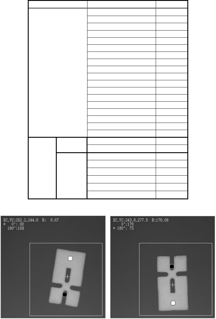
Table 110 is the example of the direction determination. Figure 133 is the result of the
recognition with the data in Table 110. The figure on the left in Figure 133 is the
recognition result obtained from the definition. The figure on the right in Figure 133 is the
recognition result of the 180 degrees rotated component.
Items to be set Set value
Alignment Group Special
Alignment Type Special
Comp. Threshold 0
Comp. Tolerance 30
Search Area (mm) 3.0
Body Size X (mm) 5
Body Size Y (mm) 9
Body Size Z (mm) 1.0
Cntr. Offset X (mm) 0.0
Cntr. Offset Y (mm) 0.0
Cntr. Offset R (mm) 0.0
Ruler Width 1
Algorithm Special 4
Base Alignment
Vision Option 1 0
Vision Option 2 0
Vision Option 3 0
Common
Data
Vision Option 4 0
Lead Group N 1
Common
Ruler Offset N 0
Lead Number: 1N 0
Reflect LL.: 1N (mm) 0.0
Lead Width: 1N (mm) 0.8
Lead Pitch: 1N (mm) 0.0
Find Pos X: 1N (mm) 0.0
N
direction
Group
1
Find Pos Y: 1N (mm) 3.0
Table 110
Figure 133