创建组件识别数据的方法.pdf - 第136页
136/178 IM-SMT-VSNDI C-0002 -000 T able 93 is the actual ex ample of the rec ognition. Item s to be set Set value Alignment Group S pecial Alignment T ype S peci al Comp. Threshold 0 Comp. T olerance 30 Search Are a (mm)…
135/178
IM-SMT-VSNDIC-0002-000
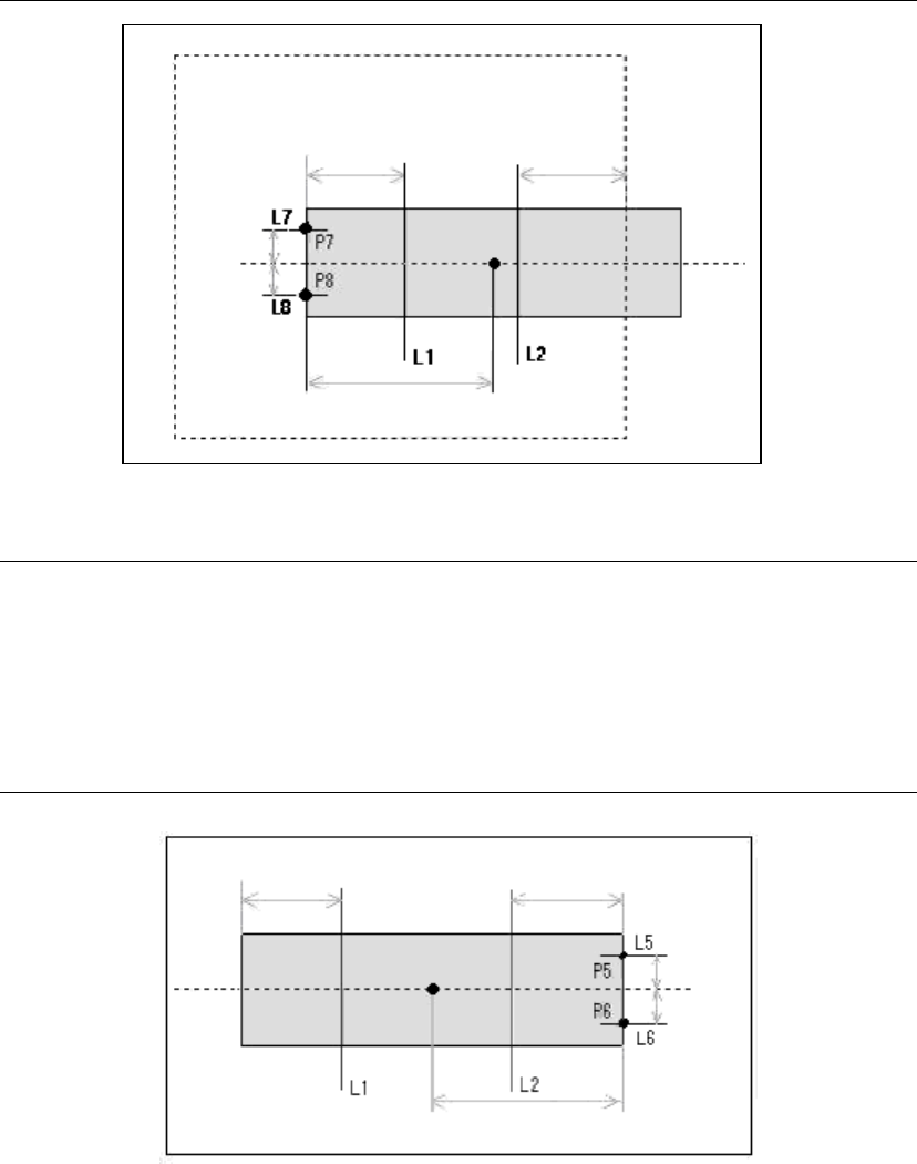
of the component, detection is not performed in that direction. In the example in Figure
110, as the search range does not encompass the right side of the component,
recognition is performed only on the left side. In this case, the search range serves as the
reference for the offset on the right side. Also, the center position of P7 and P8 that have
been determined at this point are averaged, and the result is offset by the amount of the
component size to determine the component center.
If the value is set to 1, detection is performed only on the left (upper) side, regardless of
whether the contour is entirely within the search range or not. (This is the same as the
example in Figure 110, except for the point that the component extends beyond the
search range.)
Figure 110
Note:
*4. If the value is set to 2, detection is performed only on the right (lower) side, regardless of
whether the contour is entirely within the search range or not. In this case as well, the
center position of the obtained edge positions are averaged, and the result is offset by
the amount of the component size to determine the component center. For instance, in
the example in
Figure 111
, P5 and P6 positions that have been determined are averaged,
and the resulting position is offset by the component size and determined to be the
component center. It is also possible to perform recognition on the components vertically
placed. In this case, the direction would be set to N-S, not to E-W.
Figure 111
Offset 1
Offset 1
Offset 2
Offset 2
Offset by the component size
Search range
Offset 2
Offset 2
Offset by the component size
Offset 1
Offset 1
136/178
IM-SMT-VSNDIC-0002-000
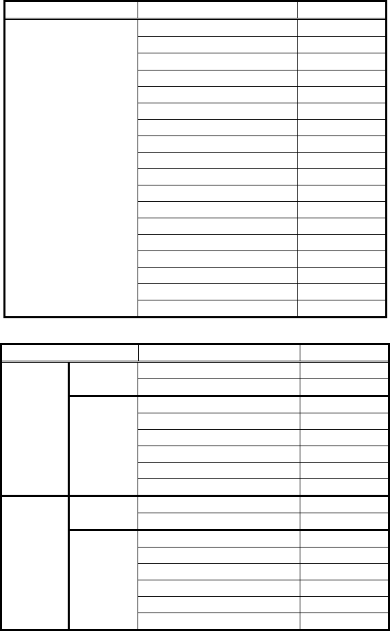
Table 93 is the actual example of the recognition.
Items to be set Set value
Alignment Group Special
Alignment Type Special
Comp. Threshold 0
Comp. Tolerance 30
Search Area (mm) 11.0
Body Size X (mm) 19.0
Body Size Y (mm) 4.0
Body Size Z (mm) 0.3
Cntr. Offset X (mm) 0.0
Cntr. Offset Y (mm) 0.0
Cntr. Offset R (mm) 0.0
Ruler Width 3
Algorithm Special
Base Alignment As Mark
Vision Option 1 0
Vision Option 2 0
Vision Option 3 0
Common
Data
Vision Option 4 0
Items to be set Set value
Lead Group E 1
Common
Ruler Offset E 0
Lead Number: 1E 0
Reflect LL.: 1E (mm) 0.0
Lead Width: 1E (mm) 0.0
Lead Pitch: 1E (mm) 0.0
Find Pos X: 1E (mm) 4.0
E
Direction
Group 1
Find Pos Y: 1E (mm) 1.5
Lead Group W 1
Common
Ruler Offset W 0
Lead Number: 1W 0
Reflect LL.: 1W (mm) 0.0
Lead Width: 1W (mm) 0.0
Lead Pitch: 1W (mm) 0.0
Find Pos X: 1W (mm) 2.0
W
Direction
Group 1
Find Pos Y: 1W (mm) 1.5
Table 93
The position of the left and right detection lines in the E/W direction are set to 4.00mm from
the contour position for E direction, 2.0mm inward for the W direction.
For the “Find Pos” of the left and right detection lines, the “Find Pos” in the E/W direction is
set to 4.0 mm inward from the contour position in the E direction, and 2.0 mm in the W
direction. The upper and lower lines are set at positions offset 1.5 mm each from the center
line.
137/178
IM-SMT-VSNDIC-0002-000
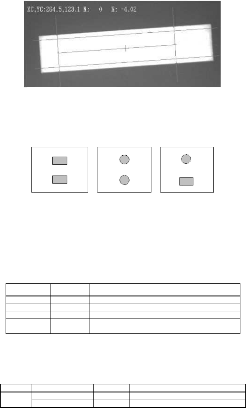
Figure 112
2.12.3-3. Mark 2
This algorithm is used for recognition of the components whose shape consists of two parts
as shown in
Figure 113
.
Figure 113
The target object is binarized, then the component is detected from the detected target object.
It is possible to perform recognition on the irregular shaped component. For binarization, both
the fixed threshold and the automatic threshold can be used.
The average center-of-gravity of the two objects is determined to be the center of the
component, and the inclination is determined as the inclination of the straight line which
connects the center-of-gravity of the two objects.
White objects are normally recognized, but it is also possible to detect black objects on
a white background.
[Recognition check items]
Items Yes / No Notes
Body Size Yes
Lead pitch No
Lead width No
Lead length No
Lead position
No
Table 94
<< Mark 2 : Items to be set for components that have two parts >>
(Special components: Special shape, algorithm: Special 2, base Alignment Type: Mark type)
Items to be set Set value
Explanation
Alignment Group Special
Common
Data
Alignment Type Special