创建组件识别数据的方法.pdf - 第160页
160/178 IM-SMT-VSNDI C-0002 -000 indicate whether t he range w as brighter or dar ker c omparing to the rotated check range. In the exam ple, the value “ 30” is set to “Vision Opti on 2”, so the diff erence in brightness…
159/178
IM-SMT-VSNDIC-0002-000
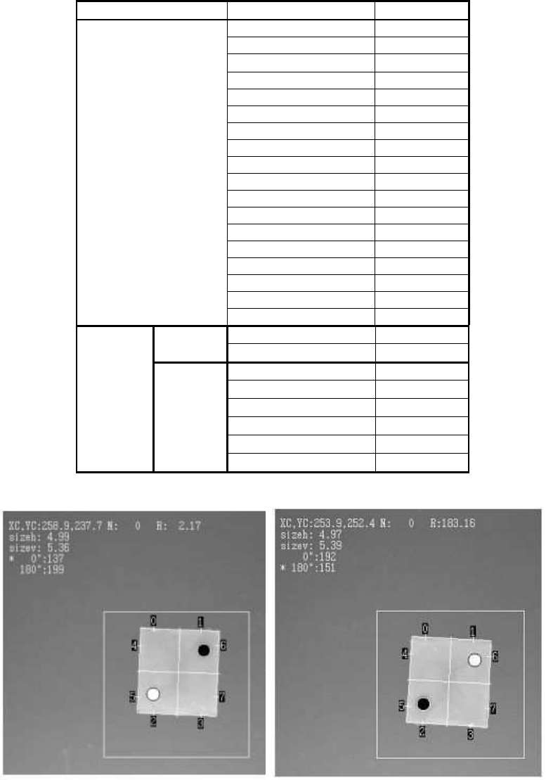
Table 106 is the example of the direction determination.
Figure 129
is the result of the
recognition with the data in Table 106. The figure on the left in
Figure 129
is the
recognition result obtained from the definition. The figure on the right is the recognition
result of the 180 degrees rotated component.
Items to be set Set value
Alignment Group Special
Alignment Type Special
Comp. Threshold 0
Comp. Tolerance 30
Search Area (mm) 4.5
Body Size X (mm) 5
Body Size Y (mm) 5.5
Body Size Z (mm) 1.0
Cntr. Offset X (mm) 0.0
Cntr. Offset Y (mm) 0.0
Cntr. Offset R (mm) 0.0
Ruler Width 1
Algorithm Special 3
Base Alignment Sp Quad
Vision Option 1 0
Vision Option 2 30
Vision Option 3 0
Common
Data
Vision Option 4 0
Lead Group N 1
Common
Ruler Offset N 0
Lead Number: 1N 0
Reflect LL.: 1N (mm)
0.0
Lead Width: 1N (mm)
0.8
Lead Pitch: 1N (mm)
0.0
Find Pos X: 1N (mm)
1.5
N
direction
Group
1
Find Pos Y: 1N (mm)
1.4
Table 106
Figure 129
The circular shapes on the figures in Figure 129 indicate the direction check range, and
160/178
IM-SMT-VSNDIC-0002-000
indicate whether the range was brighter or darker comparing to the rotated check range.
In the example, the value “30” is set to “Vision Option 2”, so the difference in brightness
between the check ranges has to be at least 30.
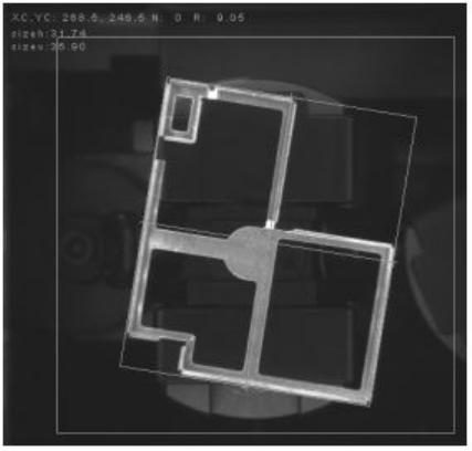
(5) Special 8: Shield recognition
The inclination of the dominant line which forms the contour of the component is
determined to be the inclination of the component.
This is used for the components whose outline of the contour is mainly consisted of the
horizontal or vertical straight lines and the entire contour are connected to each other.
Option 4: “Cut Inner /Outer Noise”, the priority to perform “Cut Inner /Outer Noise” function
and the object type are specified.
Please refer to ”2.12.3-3. Mark 2 Note*3” for details.
Figure 130
(6) Special 10: Check Upside-Down
It identifies whether the surface is the topside or the bottom side by checking the
variation of the brightness of the specified determination range.
Option 1: Threshold of 3-sigma
It sets the threshold of the brightness variation (3-sigma) within the
determination range. Dispersion value becomes larger as the brightness
variation becomes larger.
Option 2: Threshold of Average
It sets the lower limit of the Average brightness value (Ave). It is available
only when “Dispersion” is selected from the “NG condition” and used to
avoid the over determination when performing recognition by the
dispersion value.
Option 3: Judgment Flag
(This function may not be available for some old software versions.)
161/178
IM-SMT-VSNDIC-0002-000
Set the Lead Group for one side out of four sides. (Ex. N direction)
- Lead Group N: 1
- Lead Number N1: 0
- Lead pitch N1: 0
- Lead width N1: The size of the determination range X (In W/E direction,
Determination range Y)
- Reflect LL N1: The size of the determination range Y(In W/E direction,
Determination range X)
- Find Pos X N1: Determination range offset X
- Find Pos Y N1: Determination range offset Y
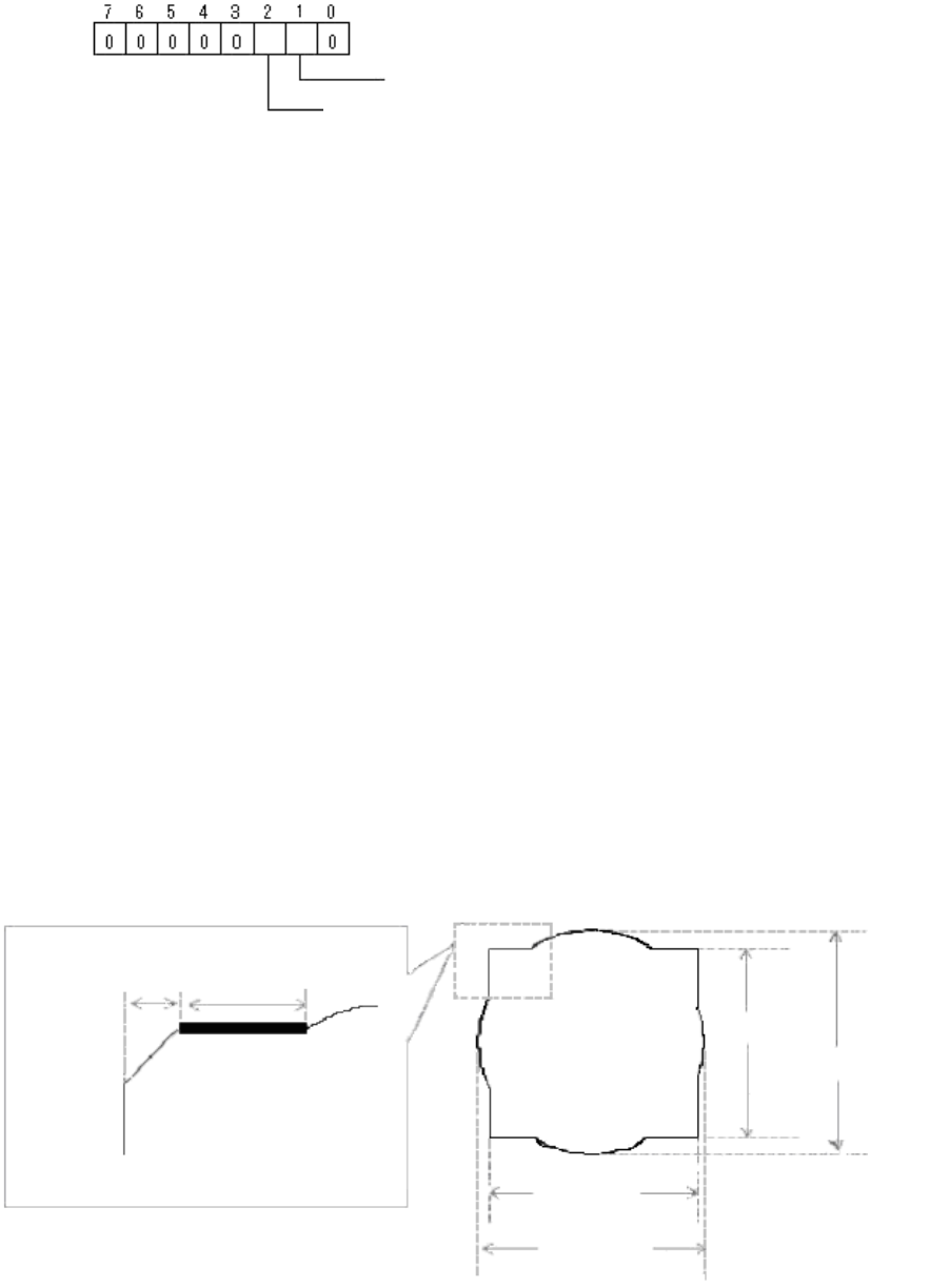
(7) Special 11: 4 Corner Fitting
This is used for positioning the generally rectangular components by using the
straight lines close to the four corners.
- Lead Group N: 1 (Set 0 for other directions)
- Reflect LL N1: Set the distance from the end surface of the rectangular part to
the straight lines where its accuracy is ensured.
- Lead width N1: Set the length of the straight line where its accuracy is ensured.
- Find Pos X N1: Set Dimension X of the square part.
- Find Pos Y N1: Set Dimension Y of the square part.
Option 4: “Cut Inner /Outer Noise”, the priority to perform “Cut Inner /Outer Noise”
function and the object type are specified.
Please refer to ”2.12.3-3. Mark 2, Note*3” for details.
Figure 131
Bit position
Check-area Offset Enable: (0:Disable, 1: Enable)
NG Condition: (0: Dispersion, 1: Non Dispersion)
Dispersion: If the brightness dispersion
value is larger than
threshold, it is determined to be an error.
Non Dispersion: If the brightness dispersion value is smaller
than
threshold, it is determined to be an error.
Lead Width
Reflect LL
Find Pos Y
Body Size Y
Find Pos X
Body Size X