创建组件识别数据的方法.pdf - 第168页
168/178 IM-SMT-VSNDI C-0002 -000 distribution on t he straight l ines, then t he detailed matc hing is perf ormed by using those positions as the c enter . As speeding u p process is not adopted for “ PTRN W hole” mode, …
167/178
IM-SMT-VSNDIC-0002-000
<<For special shape>
Mark Outsize X (mm) Sets the Body Size X.
Mark Outsize Y (mm) Sets the Body Size Y.
Area (mm
2
) Sets the area.
Outline Sets the perimeter
Table 114
3.2. Template matching (Recognition type: pattern)
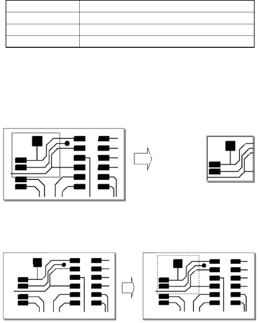
In this method, a mark that has been registered in advance is used to detect the mark that is
the closest to the registered mark from among those on the image that has been captured.
A template is created from the specified field.
Figure 136
Matching is performed on the captured image by using the registered template.
Figure 137
The position that matches most closely to the registered mark is detected.
The recognition results are detected at the sub-pixel level.
In “PTRN Outline” mode, recognition is performed by registering the contour part of the
fiducial mark as a template.
In “PTRN Graylev” mode, the straight line on each vertical and horizontal direction are set in
order to speed up the detection, and the rough position is determined by using the brightness
Template registration
Matching

168/178
IM-SMT-VSNDIC-0002-000
distribution on the straight lines, then the detailed matching is performed by using those
positions as the center.
As speeding up process is not adopted for “PTRN Whole” mode, it takes time for processing
compare to other modes. However, there is the least possibility for the detection error and it
provides the high detection accuracy.
The matching degree is calculated by normalized correlation. Therefore the overall fluctuation
in brightness does not affect the degree.
The matching degree decreases when unevenness of lighting or reflection fluctuates.
Also it does not correspond to the size variation and rotation (as it may decrease the matching
degree), it is not applicable for the objects that change size or rotate.
<< Items to be set for Matching detection >>
Shape Type --
Surface type --
Algorithm Type Selects from “PTRN Outline” ,”PTRN GrayLev” or “PTRN Whole”
Mark Threshold
--
Tolerance
Specifies the allowable matching level. When the matching level
is more than (1.0 – tolerance /100), it is determined to be
satisfactory.
Search Area Sets the detection range.
Cut Inner Noise
--
Cut Outer
Noise
--
Pattern Size X Template size X
Pattern Size Y Template size Y
Offset X Offset amount X from the center of the template
Offset Y Offset amount Y from the center of the template
Table 115
3.3 Corner detection
With this recognition method, the linear elements are detected from the contour of the object
with the largest surface area, and from those elements, those that are thought to be corners
are detected and recognized.
Caution:
In this mode, recognition should be performed only when there is only one corner in the
detection range.
If there are more than one corner in the detection range, it is impossible to determine which
coordinate of the corner to be detected.
Figure 138

169/178
IM-SMT-VSNDIC-0002-000
<< Items to be set for Corner detection >>
Shape Type Corner
Surface type Selects from Reflecting / Non reflecting
Algorithm Type Normal
Mark Threshold
Sets the binarization level.
(When 0 is specified, binarization level is set automatically.
Tolerance --
Search Area Sets the detection range.
Cut Inner Noise Selects from 0 through 9.
Cut Outer Noise Selects from 0 through 9.
Mark Outsize
Specifies the length of the segment targeted for processing
(the dimension line in
Figure 138
).
Only items with a segment equal to or longer than the value
specified here is targeted for processing.
If this is set to 0, all segments are targeted for processing.
Table 116
3.4. Top Edge detection
With this recognition method, the linear elements are detected from the contour of the object
with the largest surface area, and from those elements, those that are thought to be tips are
detected and recognized.
Caution:
In this mode, recognition should be performed only when there is only one tip in the detection
range.
If there are more than one tip in the detection range, it is impossible to determine which
coordinate of the tip to be detected.
Figure 139
<< Items to be set for Top Edge detection >>
Shape Type Tip detection
Surface type Selects from Reflect / Non reflect
Algorithm Type Normal
Mark Threshold
Sets the binarization level. (When 0 is specified, binarization level
is set automatically.
Tolerance Sets the tolerance of the tip width (specified by the Mark Outsize)
Search Area Sets the detection range.
Cut Inner Noise Selects from 0 through 9.
Cut Outer Noise Selects from 0 through 9.
Mark Outsize Sets the width of the tip portion. (The dimension line in
Figure 139.)
Table 117