创建组件识别数据的方法.pdf - 第12页
12/178 IM-SMT-VSNDI C-0002 -000 1.2 The basics of the component dat a definitions This sec tion describes how to create c omponent data in details . The component d efinition for the component that has tw o Lead Grou ps …
11/178
IM-SMT-VSNDIC-0002-000
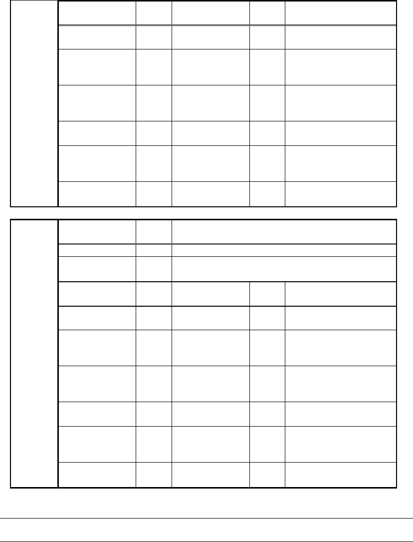
Items to be set
(Group 1)
Set
value
Items to be set
(Group 2)
Set
value
Explanation
Lead Number:
1E
Lead Number:
2E
Sets the number of
leads.
Reflect LL.:
1E (mm)
Reflect LL.:
2E (mm)
Sets the lead length of
the lead(s) on the right
on the image.
Lead Width:
1E (mm)
Lead Width:
2E (mm)
Sets the width of the
lead for the lead(s) on
the right.
Lead Pitch:
1E (mm)
Lead Pitch:
2E (mm)
Sets the pitch for the
lead(s) on the right.
Find Pos X:
1E (mm)
Find Pos X :
2E (mm)
Sets the reference
position for the lead(s)
on the right.
Find Pos Y:
1E (mm)
Find Pos Y:
2E (mm)
Items to be set
Set
value
Explanation
Lead Group W
Sets the number of Lead Group (1 or 2)
Ruler Offset W
Sets the offset amount for the detection line in
the W direction.
Items to be set
(Group 1)
Set
value
Items to be set
(Group 2)
Set
value
Explanation
Lead Number:
1W
Lead Number:
2W
Sets the number of
leads.
Reflect LL.:
1W (mm)
Reflect LL.:
2W (mm)
Sets the lead length for
the lead(s) on the left
on the image.
Lead Width:
1W (mm)
Lead Width:
2W (mm)
Sets the width of the
lead for the lead(s) on
the left.
Lead Pitch:
1W (mm)
Lead Pitch:
2W (mm)
Sets the pitch for the
lead(s) on the left.
Find Pos X:
1W (mm)
Find Pos X :
2W (mm)
Sets the reference
position for the lead(s)
on the left.
W
direction
Find Pos Y:
1W (mm)
Find Pos Y:
2W (mm)
Table 2
Caution:
In Table 2, the reference lead positions are expressed as the Find Pos.
12/178
IM-SMT-VSNDIC-0002-000
1.2 The basics of the component data definitions
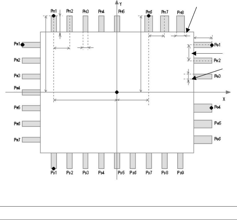
This section describes how to create component data in details. The component definition for
the component that has two Lead Groups (See
Figure 7
) is taken as an example here.
Figure 7
Note:
In
Figure 7
, the reference lead positions are displayed as the Find Pos.
In the N direction, the five leads on the left side and the three leads on the right side have
different Lead width. In a case like this, as the component cannot be defined by a single Lead
Group, it is defined by the two Lead Groups.
The tip position of the Pn1 lead is set as the reference for the first Lead Group, and from Pn1
to Pn5 leads are defines as follows:
Reference lead position X N1 : - 5.08mm
Reference lead position Y N1 : 6.00mm
ReflectLL N1 : 1.00mm
Lead width N1 : 0.40mm
Lead pitch N1 : 1.27mm
Lead Number N1 : 5
The tip position of the Pn6 lead is set as the reference for the second Lead Group, and from
Pn6 to Pn8 are defined as follows:
Length N1
N
E
W
S
Length E1
Pitch N2
Width N2
Pitch N1
Width N1
Find Pos X N1 Find Pos X N2
Find Pos Y N2
Pitch E1
Width E1
The center of the component
Find Pos Y N1
13/178
IM-SMT-VSNDIC-0002-000
<Group 2: right-side group in N direction>
Reference lead position X N2 : 3.00mm
Reference lead position Y N2 : 6.00mm
ReflectLL N2 : 1.00mm
Lead width N2 : 0.60mm
Lead pitch N2 : 1.27mm
Lead number N2 : 3
Defining the Lead Groups in this way makes it possible to define the components that have
different lead width, lead pitches and lead length.
For the E direction, in the same way, pe1 is defined as the reference for the first Lead Group
and pe4 is defined as the reference for the second Lead Group.
< 1
st
Lead Group >
Reference lead position X E1 : 7.50mm
Reference lead position Y E1 : 3.81mm
ReflectLL E1 : 1.00mm
Lead width E1 : 0.40mm
Lead pitch E1 : 1.27mm
Lead Number E1 : 3
<2nd Lead Group >
Reference lead position X E2 : 7.50mm
Reference lead position Y E2 : -1.27mm
ReflectLL E2 : 1.00mm
Lead width E2 : 0.60mm
Lead pitch E2 : 1.27mm
Lead Number E2 : 3
It is possible to define the leads by a single Lead Group in the S and W direction.
<S direction Lead Group >
Reference lead position X S1 : - 5.08mm
Reference lead position Y S1 : - 6.00mm
ReflectLL S1 : 1.00mm
Lead width S1 : 0.40mm
Lead pitch S1 : 1.27mm
Lead Number S1 : 9
<W direction Lead Group >
Reference lead position X W2 : - 7.50mm
Reference lead position Y W2 : 3.81mm
ReflectLL W2 : 1.00mm
Lead width W2 : 0.40mm
Lead pitch W2 : 1.27mm
Lead Number W2 : 7
Basically, the component data can be created in this way. However, there is a method to
create the data more simply by inputting only the minimum data on the machine.
The following section describes the process.