创建组件识别数据的方法.pdf - 第7页
7/178 IM-SMT-VSNDI C-0002 -000 Figure 3 Thus, the leads are defined as two different groups when th e leads cannot be defined as a single group due to the factor that individual lead width, lead pitch or lead length are …
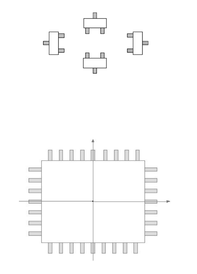
6/178
IM-SMT-VSNDIC-0002-000
Figure 1
The shape parameter is used to define the shape of the component, and defines it with a
coordinate system like shown in
Figure 2
.
Figure 2
The upper direction of the image is defined as the N direction, the lower direction as the S
direction, the direction to the right of the image as the E direction and the direction to the left
of the image as the W direction.
It is possible to define up to two groups of lead information for each direction.
The Lead Group consists of leads that have the same lead width, lead pitch, and lead length.
In the case shown in
Figure 2
, as all of the leads in one direction have the same lead width,
lead pitch and lead length, they can be defined as one Lead Group.
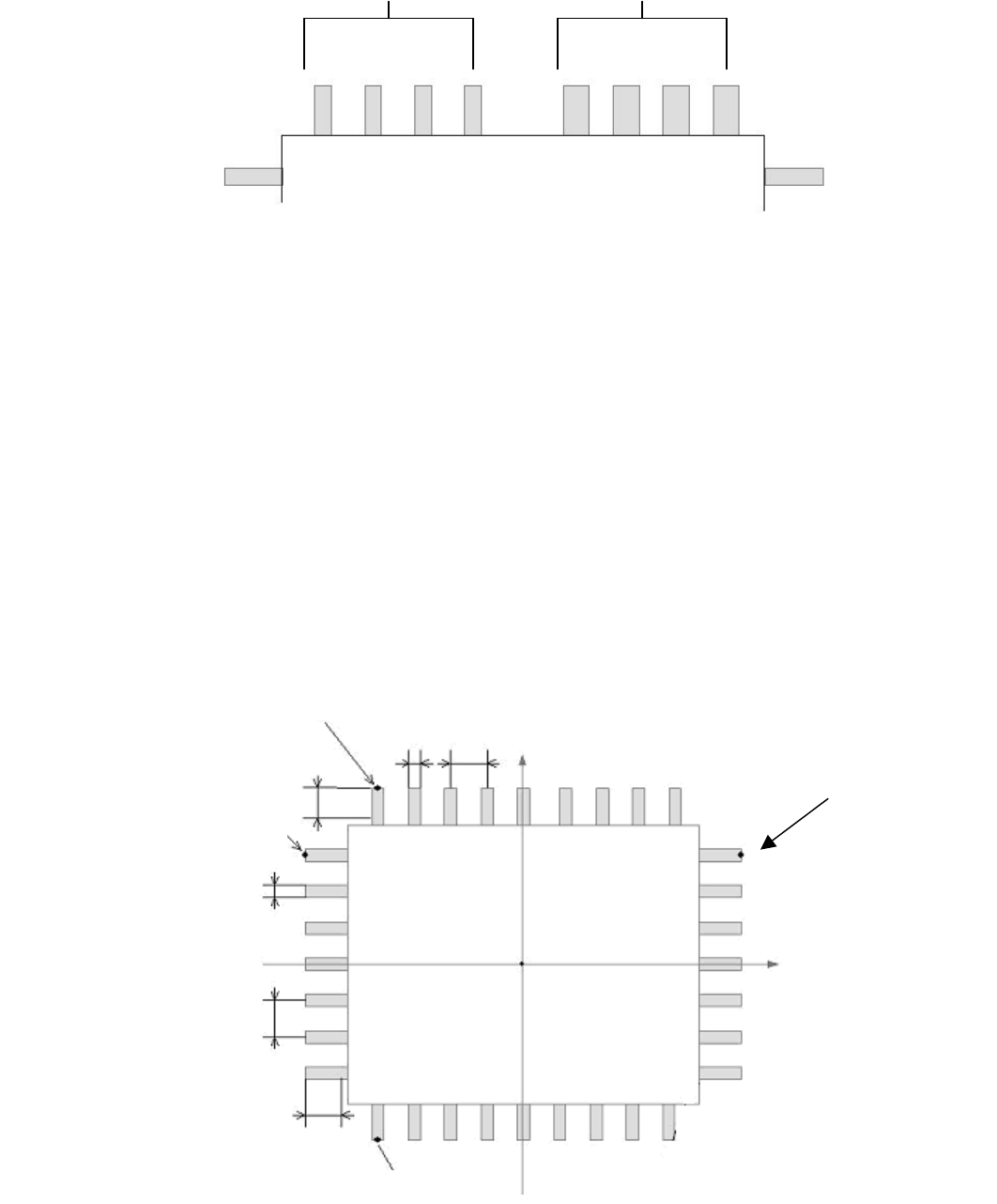
On the other hand, in the case shown in
Figure 3
, as the lead width of the leads are different,
they cannot be defined as a single Lead Group, but are divided into two Lead Groups for
definition purposes.
Normal
90 degrees
180 degrees
270 degrees
Center of the component
W
N
E
S
Y
X
7/178
IM-SMT-VSNDIC-0002-000
Figure 3
Thus, the leads are defined as two different groups when the leads cannot be defined as a
single group due to the factor that individual lead width, lead pitch or lead length are different
or the lead pitches are not constant. (The Lead Groups can be defined up to 2 groups for
each direction.)
Each Lead Group can be defined based on the position and width of the reference lead, lead
length, lead pitch and number of the leads.
For a component shown in
Figure 4
, the leads in one direction can be define based on the
following factors:
- the position of the reference lead
- the lead length
- the lead width
- the lead pitch
- the number of the leads
In order to define the leads of the component as a whole, Lead Groups need to be defined for
each direction.
Figure 4
Group 1 Group 2
N
N direction reference lead position
E direction reference lead position
W direction reference lead position
S direction reference lead position
X
Y
Lead
width
Reflect Lead Length
Lead
pitch
Lead width
Lead pitch
Component center
Reflect Lead Length
N direction
E direction
S direction
8/178
IM-SMT-VSNDIC-0002-000
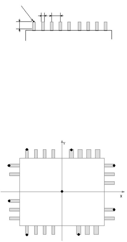
For example, the row of the leads in N direction shown in
Figure 5
can be defined by the
coordinates of the tip position (
part in the figure) of the leftmost lead as a reference lead
position X and reference lead position Y, while the lead length will be defined as “length”, the
lead width as “width”, the lead pitch as “pitch” and the number of the lead as “n”.
Figure 5
It is also possible to define the row of the leads in S, E and W direction in the same way.
When defining these directions, the points used as the reference are as follows:
- The S direction: the leftmost lead
- The E direction: the uppermost lead
- The W direction: the uppermost lead
(In
Figure 5
, the lead with
mark is the reference lead, and its tip is the reference lead
position.)
As shown in
Figure 6
, when the leads in a single direction have different width and pitches,
they are divided into two groups and then defined. For example, the row of leads in the N
direction shown in
Figure 6
can be defines as follows:
Figure 6
<< Group 1: Left-side group in N direction >>
Reference lead position X1
Reference lead position Y1
Lead length: length 1
Reflect Lead Length
Lead
width
Lead pitch
N direction reference lead position
N
E
W
S
Group 1
Group 1
Group 2
Group 1
Group 2
Group 2
Group 2
G
roup 1
Component center
N direction